


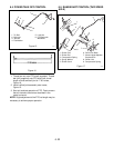

7 -26
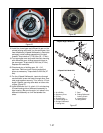
10.Remove the differential assembly from the tractor.
11.Using wire cutters, remove wire securing bolts on
each side of worm gear. Secure differential
assembly upright in vise. (4 Speed Swiftamatic
only).
12.Remove bolts securing clutch housing to worm
gear. Remove clutch housing, gears, and shims.
13.Turn worm gear over and remove pinned housing
and gears.
14.Tilt differential mechanism and remove from worm
gear. The mechanism does not ride on the inside
surface of the gear.
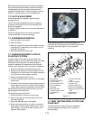
15.Disassemble the differential mechanism-carefully
checking the bore of the gears and the spider arms
for scoring. Check the backs of the shifting train
pinions.
16.Reassemble the differential mechanism using new
thrust needle bearings if any other parts were
replaced. On the two spider arms with snap ring
grooves at the end, assemble in this sequence:
spider gear, shifting train pinion, bearing, spacer
and snap ring. On the other two arms assemble in
this sequence: spider gear, race, bearing, spacer
and snap ring.
17.Tilt the differential mechanism and install it in the
worm gear.
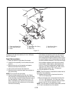
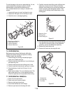
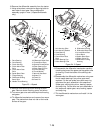
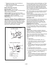
Figure 23 - 4-Speed
1. Race Bearing
2. Cone Bearing
3. Clutch Housing
4. Clutch Worm Gear
Shim
5. Clutch Worm Gear
Shim
6. Spider Bevel Gear
7. Flange Bushing
8. Differential Shifting
Bevel Gear
9. Needle Thrust Bearing
10.Differential Bevel Gear
11.Pinned Bevel Gear
12.Splined Pinned Shifter
13.Roller Bearing Cup
14.Roller Bearing Cone
15.Pinned Housing
16.Thrust Washer
17.Worm 8 Start Gear
18.Spider Pin
19.Dowel Pin
20.Dowel Pin
1
2
3
4
5
6
7
8
9
10
11
12
13
14
15
11
10
17
16
19
18
6
8
20
7
9
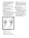
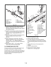
Figure 24 - 2-Speed
1. Axle Housing Shim
2. Axle Housing Gasket
3. Race Bearing
4. Cone Bearing
5. Clutch Worm Gear
Shim
6. Roller Bearing Cup
7. Roller Bearing Cone
8. Differential Housing
9. Differential Bevel Gear
10.4 Lead Worm Gear
11.Drive Block
12.Spider Bevel Gear
13.Spider Pinion Pin
14.Differential Locking
Housing
1
2
3
4
5
6
7
8
9
10
9
11
12
11
12
13
14