


4 -12
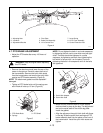
• To adjust the forward clutch, put the direction
control in the forward position. Loosen the control
extension rod rear set of jam nuts on the fwd-rev
control rod. Adjust the forward nut until the large
spring coils are .010" (.254mm) apart. Hold the
forward nut and jam with the rear nut.
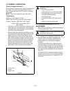
4.5 HI/LOW GEAR CLUTCH ADJUSTMENT
• After every 25 hours of operation, check the
adjustment of the gear clutch.
• The clutch is adjusted correctly when the gear shift
lever is in the "HIGH" or "LOW" position and the
spring coils are .010" (.254 mm) apart.
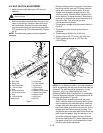
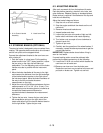
• To adjust the "HIGH" clutch, loosen and separate
the hi-low control rod jam nuts on the rear of the
control extension rod. Put the gear shift lever in the
"HIGH" position. Adjust the nut (front) near the
spring until the spring coils are .010" (.254 mm)
apart. Move the gear shift lever to the "NEUTRAL"
position. Hold the nut adjusted to the spring and
jam with the other (rear) nut (Figure 4).
• To adjust the "LOW" clutch, loosen and separate
the hi-lo control rod jam nuts on the end of the
control extension rod. Put the gear shift lever in the
"LOW" position. Adjust the nut (rear) near the
spring until the spring coils are 0.10" (.254 mm)
apart. Move the gear shift lever to the "NEUTRAL"
position. Hold the nut adjusted to the spring and
jam with the other (front) nut.
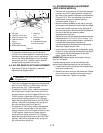
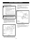
4.6 STEERING BRAKE ADJUSTMENT
(APPLICABLE MODELS)
• Park the unit in a level area. Put the parking brake
handle in the "OFF" (down) position. Loosen the
jam nuts on the right and left brake rod assemblies
(Figures 2 & 3). Turn the adjusting nuts until the
brake handle cross bar is parallel with the
instrument panel (Figure 1).
• Move the brake handlebar all the way to the right
and measure the distance from the right end edge
of the brake handle cross bar to the right side of
the instrument panel. Move the brake handlebar all
the way to the left and make the same
measurement on the left.
• Adjust the nuts until the difference between the two
measurements is 1/2" to 3/4" (13 to 19 mm). Turn
both adjusting nuts the same amount, clockwise to
increase the measurement difference or
counterclockwise to decrease the measurement
difference. Tighten the jam nuts.
• Loosen the jam nuts below the compression spring
(Figure 4) on the right side of the tractor and adjust
until one has the desired tension for the right
brake. Tighten the jam nuts.
IMPORTANT:
Replace brake shoes before lining is
worn to rivet heads.
If correct braking action cannot be achieved after
performing the above procedures, do the following:
1. Loosen the 5/16-24 nut and bolt which fastens cam
lever arm to brake cam.
2. Remove cam lever arm from the brake cam. Rotate
the cam lever arm one spine to the rear and put
back on brake cam. Tighten nut and bolt.
WARNING:
Stop the engine before adjusting
the gear clutch.
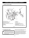
1. Jam Nuts
2. Fwd-Rev Control Rod
3. Control Extension Rod
4. Fwd-Rev Neutral
Spring
5. Large Spring
6. Brake Rod Assembly
7. Adjusting
nuts
8. Fwd-Rev Lever
Assembly
9. Adjustment Bracket
10. Cam Lever Arm
Figure 3
OH0181
1
1
7
7
7
2
3
4
5
6
8
9
10
7
1