


6 -21
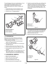
11.Put a film of grease on the axle splines. Slide the
wheel hub on the axle followed by a flat washer
and lock nut. Tighten the nut to a torque of 80 ft.-lb.
(108 Nm). Tighten the set screw.
12.Mount the tire assembly to the wheel hub.
Left Side Installation:
1. Raise and block the left side of the tractor.
2. Unbolt the tire assembly from the wheel hub and
remove.
3. Remove the axle nut, flat washer and spacer.
Remove the wheel hub set screw.
4. Use a puller and remove the wheel hub.
5. Remove the four bolts that retain the end plate to
the axle housing.
NOTE:
Do not remove the end plate.
6. Slide the brake assembly over the axle. Rotate
until the holes in the end plate align with the holes
in the axle housing (cam lever arm at the 12 o’clock
position). Retain with four 3/8-16 x 7/8" bolts.
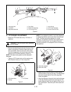
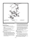
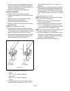
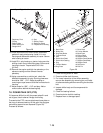
7. Remove the bolt which attaches the left handlebar
support to the advance casting. Install the pivot
stud in the same location. See Figure 14.
8. Place the following on the pivot stud:
- E-Ring
- .656" x 1.312" x .095" Flat Washer
- Pivot Plate
- .656" x 1.312" x .095" Flat Washer
- E-Ring
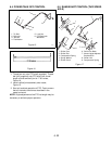
9. Connect the brake link rod to the pivot plate and
the cam lever arm. Retain with a .406" x .812" x
.065" flat washer and a .09" x .75" cotter pin at
each end.
10.Slide the rear of the left hand brake rod assembly
into the left end of the handlebar weldment from
the front. Connect the adjustment bracket to the
pivot plate with a .375" x .75" clevis pin, two .406" x
.812" x .065" flat washers, and a .09" x .75" cotter
pin.
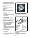
11.Put both spacers on the axle.
NOTE:
The short spacer only is used with the wheel
hub for the 8.50 x 8 tire assembly.
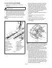
12.Replace the set screw in the wheel hub with a
7/16-14 x 3/4" set screw.
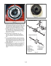
13.Mount the brake drum to the wheel hub with four
1/2-13 x 1-3/8" bolts and 1/2-13 lock nuts. Four
1/2-13 x 1-5/8" bolts are required when the wheel
hub for the 8.50 x 8 tire assembly is used.
NOTE:
The valve stem is turned to the outside, and the
1/2-13 lock nuts should be on the outside.
14.Put a film of grease on the axle splines. Slide the
wheel hub on the axle followed by a flat washer
and lock nut. Tighten the nut to a torque of 80 ft.-lb.
(108 Nm). Tighten the set screw
15.Mount the tire assembly to the wheel hub.
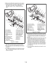
Figure 14
1. Pivot Stud
2. Flat Washer
3. E-Ring
4. Pivot Plate