


6 -18
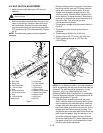
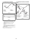
6.1 HANDLEBAR ASSEMBLY
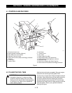
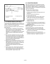
1. On Swiftamatic tractors, disconnect the cotter pin
that holds the Swiftamatic control lever to the
shifter weldment. Disconnect the extension spring
from the control lever and slide the control lever
rearward until it stops against the instrument panel.
See Figure 10.
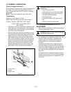
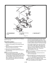
2. Position the handlebar right side up. Move the left
handle of the handlebar under the right side of the
frame and the wiring harness. Proceed across the
engine and out between the left side of the frame
and the PTO control. Rotate the handlebar into the
mounting position.
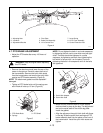
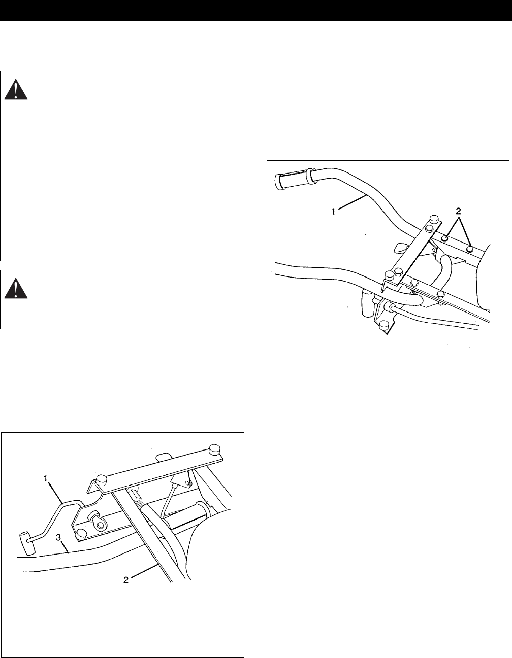
3. Retain the handlebar in position with four
3/8-16 x 1.25 Grade 8 bolts and lock nuts. The
Grade 8 bolt has six marks on the head. See
Figure 11.
4. Reassemble the Swiftamatic control lever linkage
and connect the wiring harness.
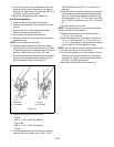
5. Mount the Hi-Lo gear control handle assembly and
hand lever pivot to the left handle with a
1/2-13 x 3.50 bolt and 1/2-13 thin lock nut. See
Figure 12.
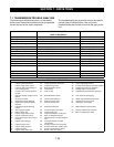
SECTION 6 - STEERING & CONTROLS
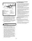
CAUTION:
Before performing any service or
adjustments:
• Turn PTO switch "OFF".
• Park mower on a hard, flat, level surface.
• Place steering control levers in neutral
lock (fully outward) position.
• Set parking brake.
• Turn ignition switch "OFF" and remove
key.
• Wait for blades and all moving parts to
stop.
• Disconnect spark plug wire(s) from spark
plug(s) and place wire(s) away from plug.
WARNING:
MOVING PARTS can cut or
amputate body parts. ALWAYS wait for
moving parts to stop before unit maintenance
or service.
Figure 10
1. Control Lever
2. Frame
3. Handlebar
Figure 11
1. Handlebar
2. Grade 8 Bolt