9
INSTALLATION
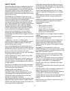
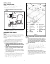
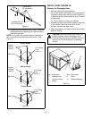
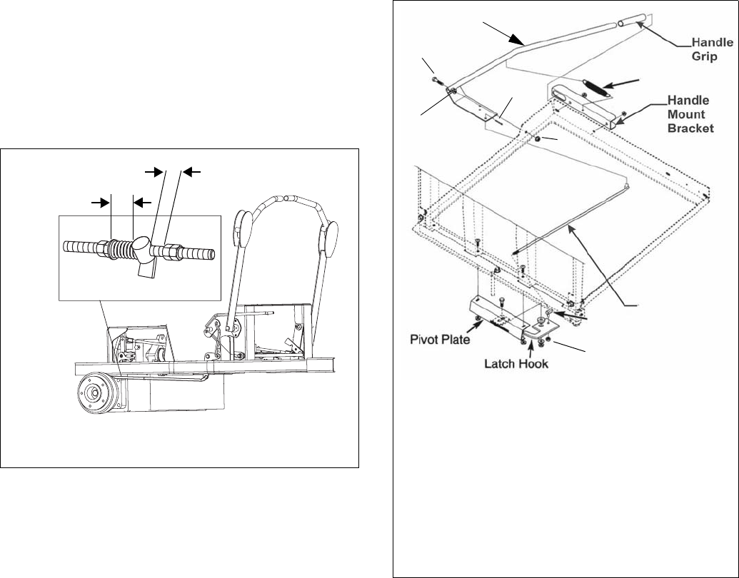
Adjust the Parking Brake
NOTE: The additional weight of the grass container
requires a parking brake re-adjustment.
1. Remove the rear wheels.
2. Set the spring length and return gap as shown
below.
3. Replace the rear wheels. Tighten the lug nuts to
51–72 lb-ft (69–97 N•m).
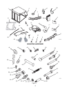
Assemble the Grass Container
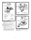
Figure 4
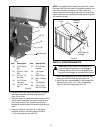
NOTE: Use three or more people to install the collector
box on the main frame. The weight and bulk of the grass
collector make it difficult to install safely without
assistants.
1. Slide the lift handle (item 14) into the slot of the
handle mount bracket on the collector box.
NOTE: You may need to remove the grip on the lift
handle to fit the handle through the slot.
2. Connect the extension spring to the open hole in
the handle mount bracket and then to the lift handle
(item 14).
3. Connect the lift handle to the grass container with
one 3/8-16 x 2 hex bolt (item 27) and two 3/8-16
flange nuts (item 28).
4. Install the ball joint on the latch rod about half way
down the threads on the latch rod so some thread is
available for adjustment.
5. Connect the ball joint (item 29) to the latch hook on
the grass container with one 5/16-24 hex nut
(item 31) and one 5/16 lock washer (item 32).
6. Connect the latch rod to the lift handle with a
3/32 x 3/4 cotter pin (item 33).
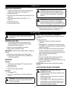
Install the Mounting Frame and Grass Container
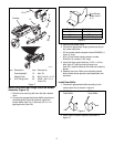
Figure 5
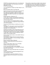
1. Remove the hardware holding the rear bumper to
the unit frame and then install the left lower frame
leg on the frame with three 3/8-16 x 3 hex bolts
(item 24) and 3/8 lock nuts (item 19). Repeat for the
right lower frame leg.
NOTE: Do not remove the bumper from the unit.
2. Install the main frame on the lower frame legs with
two 3/4-10 x 1-1/2 hex bolts (item 34) and two
3/4-10 nylon lock nuts (item 35) and with two
1/2-13 x 1 hex bolts (item 36) and two pivot frame
handles (item 37).
3. Have two people hold the grass container in
position while a third person connects the container
to the main frame with two detent pins (item 43),
two 5/8 flat washers (item 44) and two 5/32 x 2-5/8
hair clips (item 45).
Figure 3
OF3303
1-1/4-in.
(3.18 cm)
1/16-in. (1.59 mm)
Figure 4
14
27
28
30
29
28
33
31, 32
42
Item Description
14 Lift Handle
27 3/8-16 x 2 Hex
Bolt
28 3/8-16 Flange
Nuts
29 Ball Joint
30 Latch Rod
Item Description
31 5/16-24 Hex Nu
t
32 5/16 Lock
Washer
33 Rue Ring Cotter
Pin
42 Spring


