


10
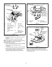
4. Connect the left and right door opening linkages to
the main frame with one Rue-Ring cotter pin
(item 33) per side.
5. Test the function of the dump mechanism by pulling
the lift handle away from the grass container and
then lifting upward. The container should pivot
backwards toward the ground and the door should
open.
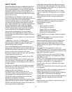
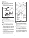
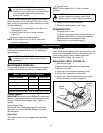
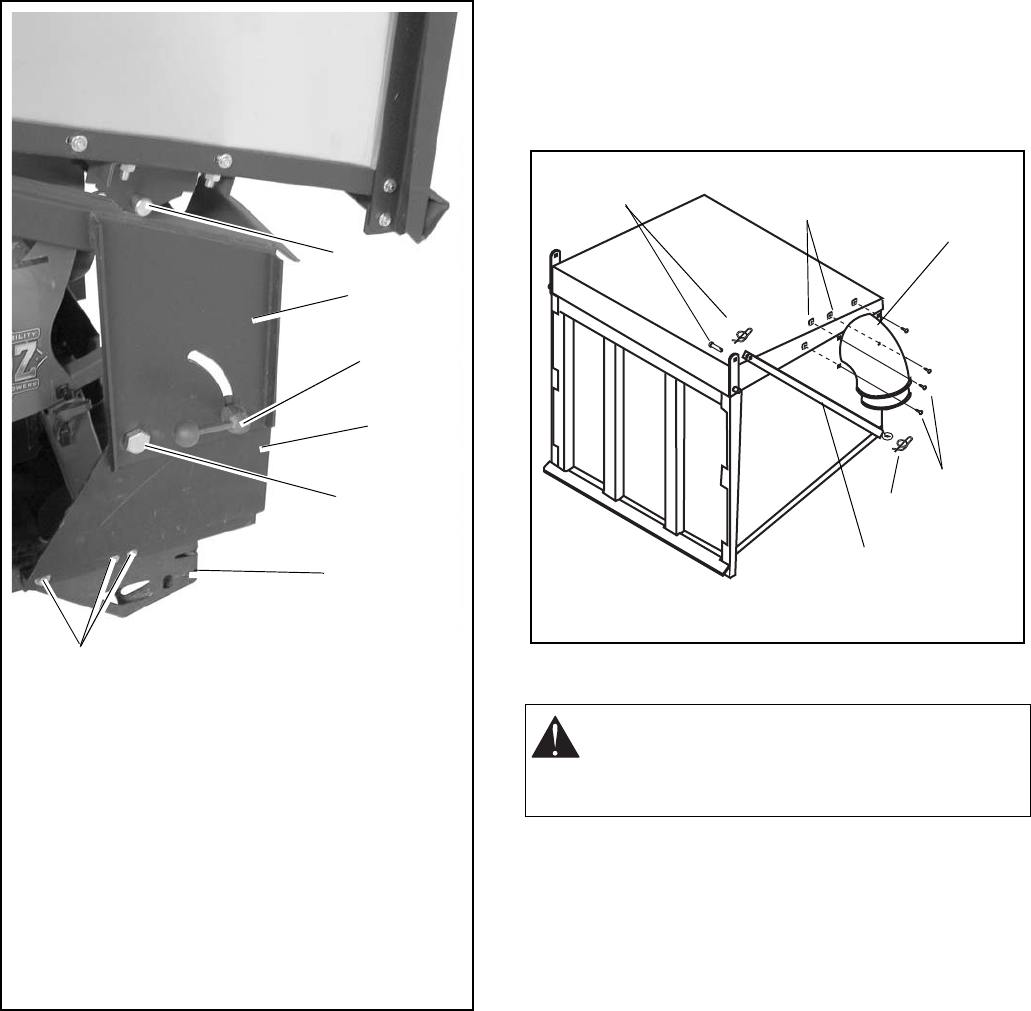
6. Install the collector inlet (item 2) on the grass
container with four mounting clamps and four
14 x 3/4 panhead screws (item 24).
NOTE: Two people should install the grass inlet. Install
the grass inlet from the inside of the grass container and
point the inlet down to the ground. Then, while one
person aligns the mounting clamps with the holes in the
side of the aluminum container, the other person tightens
the machine screws.
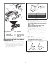
INSTALL COUNTERWEIGHTS
1. Install the weight plate on the front axle with two
clevis pins (item 25) and hair pins (item 12).
2. Install the four counterweights on the bracket and
secure with two 5/16-18 x 4-1/2 carriage bolts
(item 23) and two wing knobs (item 10).
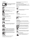
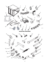
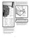
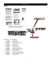
Figure 5
Item Description
19 3/8-16 Nyloc
Nut
24 3/8-16 x 3 Hex
Bolt
34 3/4-10 1-1/2
Hex Bolt
35 3/4-10 Nylon
Lock Nut
36 1/2-13 x 1 Hex
Bolt
Item Description
37 Pivot Frame
Handle
39 Left Frame
Leg
41 Main Frame
43 5/8 x 3 Detent
Pin
44 5/8 Washers
45 5/32 x 2-5/8
Hair Pin Clips
43, 44, 45
41
36, 37
39
34, 35
Rear Bumper
19, 24
CAUTION: Always install counterweights on
front axle before operating unit with bagger
attached. Always remove counterweights from
front axle when bagger is removed from the unit.
Figure 6
Mounting
Clamps
24
2
Door Opening
Linkage
33, 46
33