


35
Check the alternator voltage regulator output (if used)
at every period maintenance inspection. Over charging
is a common cause of battery failure.
Battery Charger
Under normal conditions, the engine alternator will
have no problem keeping battery charged. When unit
has set for an extended period of time without
operation and the battery has been completely
discharged, a battery charger will be required for
recharging.
Charging a New Battery
IMPORTANT: DO NOT fast charge. Charging at a
higher rate will damage or destroy battery.
ALWAYS follow information provided on battery by
battery manufacturer. Contact battery manufacturer for
extensive instructions to charge battery.
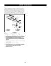
1. Put unit into service position to gain access to
battery.
2. Disconnect Negative (-) cable first, then Positive
(+) cable.
3. Remove hold down and remove battery.
4. Place battery on bench or other well-ventilated
place where electrolyte spill will not create
damage.
5. Connect Positive (+) lead of charger to Positive (+)
terminal. Connect Negative (-) lead to Negative (-)
terminal.
6. Charge battery at two and half amps for ten hours
or until all cells are gassing freely.
7. Reinstall battery into unit and connect Positive (+)
cable first, then Negative (-) cable.
SWITCHES
Switches either open a circuit to stop current flow or
close and allow current to flow through.
A normally open (N.O.) switch prevents current flow
until the switch is actuated, completing the circuit and
allowing current to flow through it. An example is a light
switch - the lights are off until the switch is actuated
and the lights go on.
A normally closed (N.C.) switch allows current to flow
until the switch is actuated, breaking the circuit and
stopping current flow through it. An example is an
ignition switch that grounds the magneto when in the
off position (completing the circuit) but opens the circuit
when in the ON position allowing the engine to operate.
Switches are selected with regard to Current rating
(contacts must be of sufficient size to carry the required
current), Voltage rating (switches insulated for specific
voltages), Case or housing (switches that are exposed
to moisture and must be sealed to prevent moisture
from entering), and Actuating type (push, pull, rotary,
momentary contact, or micro switches).
NOTE: Check that the connections to the switches are
secure and that a switch is being activated properly
before performing electrical test on switches. (Safety
switches on speed selector and clutch levers may be
out of adjustment and not activating.)
IMPORTANT: When checking switches, remove them
from their respective circuit by disconnecting the wires
from the switch at the connector(s). Damage could
result to the meter or machine components if switches
are left in.
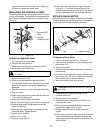
Normally Open Switch
To test a normally open switch (key, headlight, safety,
or seat) connect the ohmmeter across the switch
terminals. Meter should indicate open circuit (infinite
resistance). Activate the switch. The ohmmeter should
read up scale to zero resistance (Close Circuit). This
indicates the switch is operating properly. Also check
from each terminal to the switch case (if case is metal).
reading should show infinite resistance indicating no
short to ground.
Variation from test results described indicates a
defective switch.
Normally Closed Switch
To test a normally closed switch connect the ohmmeter
across the switch terminals. Meter should indicate a
closed circuit (zero resistance). Activate the switch and
the meter should move to open circuit (infinite
resistance). Check from each terminal to ground
(switch case). Meter should show open circuit (infinite
resistance).
Variation from test results described indicates a
defective switch.
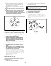
Ignition Switch
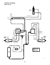
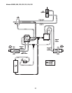
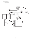
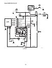
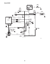
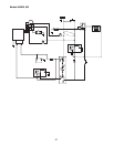
NOTE: Refer to the wiring diagram of the unit involved
to determine switch functions and test using the meth-
ods described.
The ignition switch incorporates a number of functions,
although not all functions are used on all equipment.
The switch has three positions: OFF, RUN, and a
momentary contact START position. Use an ohmmeter
to check the continuity of the switch in each position.
OFF Position - Should be continuity between contacts
G and M. These connections ground the engine
magneto and stop the engine in the OFF position.
RUN Position - Should be continuity between contacts
B and A. These connections supply power to the rest of
WARNING: FROZEN BATTERIES CAN
EXPLODE and result in death or serious
injury.
DO NOT charge a frozen battery. Let the
battery thaw out before putting on a charger.