


21
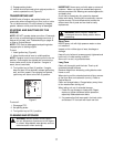
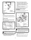
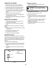
Figure 11
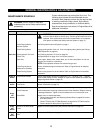
TIRES
Before each use, make a visual check of tires.The
correct air pressure is 12-15 psi (83-103 kn/m
2
) for the
rear tires, and 20-25 psi (138-172 kn/m
2
) for the front
tires.
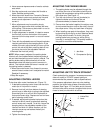
MOWER BLADES
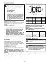
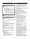
NOTE: If mower is used under sandy soil conditions,
replace mower blades when air lifts become eroded
through at ends (Figure 12).
Figure 12
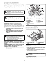
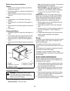
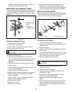
Sharpening Mower Blade
1. Turn the engine off. Remove the ignition key.
2. Remove the bolts, lock washer, the flat washers,
and blades from the spindle shafts.
3. Sharpen the beveled edges of the blades in a
straight line. Do not change the angle of the
beveled edge. If more than 0.5 inches (12.7 mm)
are removed from the width of a blade, discard the
blade. Make sure the sharpened blades are
balanced. Balance must be held within 1.3 inch
ounces.
4. Put the blades, the flat washers, lock washers, and
the bolts back on the spindle shafts.
5. Tighten the bolts to a torque of 70 ft. lbs (95 Nm).
Put the ignition wires back on the spark plugs.
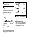
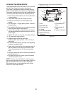
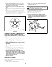
STEERING CONTROL NEUTRAL
ADJUSTMENT
If the unit has excessive creep when the control levers
are in neutral, adjust as follows: (Figure 13)
Figure 13
1. If hydraulic system is cold, run unit for a minimum
of five minutes, then shut off unit.
2. Make sure both control levers are in neutral. Raise
hood.
3. With the unit up to and facing a wall, jack the unit
up so that both drive wheels are off the ground.
CAUTION: Use sturdy gloves or padding to
protect hands when working with mower
blades.
3
6
2
4
5
1
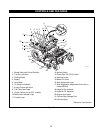
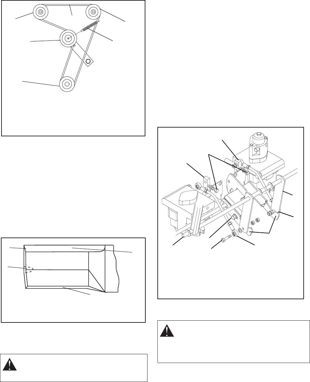
1. Hydro Belt
2. Spring
3. Idler
4. Engine Sheave
5. Right Hand
Hydrostat
6. Left Hand Hydrosta
t
OF 1631
4
2
3
1
1. Cutting Blade
2. Square Corner
3. Air Lift Erosion
4. Air Lift
WARNING: This adjustment requires operation
of the engine and opening of hood. Use extreme
care to avoid contact with moving parts and hot
surfaces. Be sure rear of unit is well supported
and secure before starting engine.
1. Stop Bolts
2. Pump Levers
3. Front Ball Joints
4. Control Levers
5. Parking Brake
Interlock
6. Clamping Bolt and
Slot
7. Mounting Bolt
OF 1820
1
2
2
4
3
5
3
7
6
4