


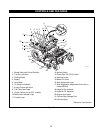
22
4. Have someone depress center of seat to activate
seat switch.
5. Start the engine and run at about half throttle or
faster. Release parking brake.
6. Move the control levers from Forward to Reverse
several times to make sure controls are free and
check neutral adjustment. If binding is found,
correct it.
7. Minor adjustments may be made by simply
adjusting the stop screw which contacts the lever
on the pump. The screw may be turned in or out to
bring the unit into neutral.
8. If major adjustment is needed, it is best to remove
the front ball joint from the bottom of the control
levers and turn the stop screw in or out until neutral
is found.
9. Then, with the adjustable arms of the parking brake
interlock positioned so the clamping bolt is in the
middle of the slot, adjust the ball joint on or off the
control link rod so that their mounting bolts fit into
the slot at the end of the adjustable interlock.
10.Reinstall the front ball joint(s)
NOTE: When properly adjusted, the parking brake
interlock will move upward when the parking brake is
set and hold the steering control levers in neutral. The
parking brake starting interlock switch will not be
depressed unless the steering control levers are in
neutral. The interlock holds the levers in neutral until
the parking brake is released.
11.Move the control levers, from forward to reverse
several times to make sure it is adjusted to neutral.
Readjust if necessary.
12.Stop the engine.
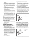
ADJUSTING CONTROL LEVERS
To be done after neutral has been set. (Figure 13).
1. If desired the steering control levers can be set to
match (be in line) when in neutral.
2. Remove front ball joint from bottom of steering
control lever on side which is going to be adjusted.
Screw ball joint on or off link rod to hydrostat so
that control levers align. Replace rod end on lower
part of steering control lever.
3. If needed, adjust parking brake interlock so that
interlock is able to move up when both steering
control levers are in neutral. To do this, loosen the
clamping bolt on the adjustable member of the
interlock and slide it in either direction until the
interlock moves up and latches the ball joint
mounting bolts.
4. Tighten the clamping bolt.
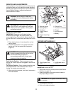
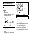
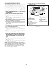
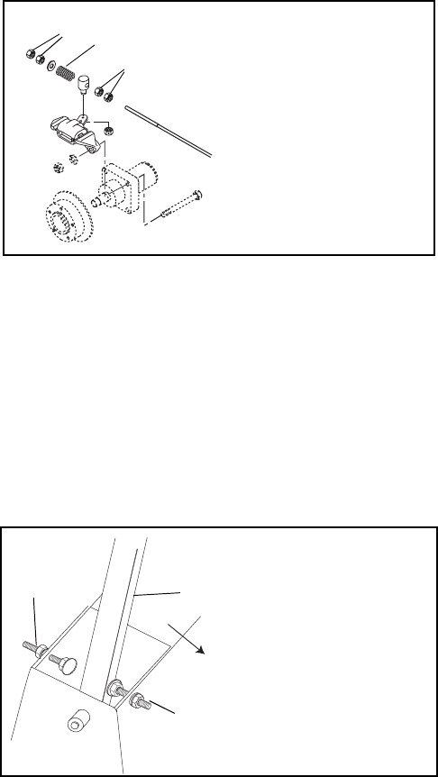
ADJUSTING THE PARKING BRAKE
1. The parking brake may be adjusted through the
use of the jam nuts on the brake rod which push
against the compression spring which pushes on
the caliper arm. See Figure 14.
2. Turn the nuts further on the rod (clockwise) to
tighten the brake and further off the rod
(counterclockwise) to loosen the brake.
3. Ensure when the brake is applied, the caliper arms
do not contact the return nuts on the rods in front of
the caliper arms. If they do, back them off slightly.
4. When installing new pads in the calipers, they must
be burnished by driving for a short distance (about
200 feet) with the brake. To do this, bring the
parking brake lever part way up, while driving
normally (in a straight line). This quickly breaks-in
the pads for maximum effectiveness.
Figure 14
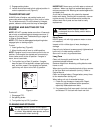
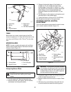
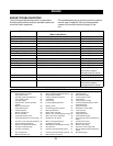
ADJUSTING UNIT TO TRACK STRAIGHT
Check and adjust tire pressure. Increase pressure on
side unit tracks to. DO NOT exceed maximum
recommended tire pressure (refer to Specifications).
If tire pressure adjustment does not solve tracking
problem, the limiter bolts at base of handles can be
adjusted. See Figure 15. Front bolts are for forward
and rear bolts are for reverse. Lengthen bolts (move
closer to lever) on side which is too fast.
Figure 15
2
1
1
1. Jam Nuts
2. Compression Spring
PF 1732
1
2
1
Front
1. Limiter Bolt
2. Lever