


Beforeassemblingthe patioheater,use the parts
list to check that all necessaryparts have been
included.Inspectpatio heaterfor damageas you
proceed.Donotassembleoroperatethepatioheater
if it appearsdamaged.If youhavequestionsduring
the assembly process, call 1-888-317-7642,
8am- 8pmCST,MondaythroughFriday.
CAUTION:
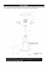
Removeall partsand hardwarefrom shippingbox.
Referto thepartslistandhardwarepackillustrations
andassemblethepatioheateron a protectivework
surfaceto avoidscratchingheatersurfaces.
• Protective gloves
• Eye protection
• One #2 Phillips Head Screwdriver
• One Adjustable Wrench
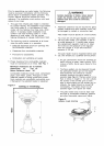
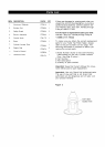
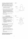
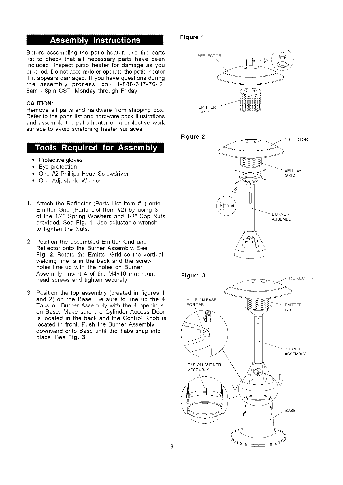
Attach the Reflector (Parts List Item #1) onto
Emitter Grid (Parts List Item #2) by using 3
of the 1/4" Spring Washers and 1/4" Cap Nuts
provided. See Fig. 1. Use adjustable wrench
to tighten the Nuts.
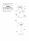
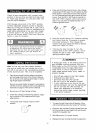
2. Position the assembled Emitter Grid and
Reflector onto the Burner Assembly. See
Fig. 2. Rotate the Emitter Grid so the vertical
welding line is in the back and the screw
holes line up with the holes on Burner
Assembly. Insert 4 of the M4xl0 mm round
head screws and tighten securely.
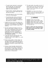
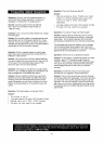
3. Position the top assembly (created in figures 1
and 2) on the Base. Be sure to line up the 4
Tabs on Burner Assembly with the 4 openings
on Base. Make sure the Cylinder Access Door
is located in the back and the Control Knob is
located in front. Push the Burner Assembly
downward onto Base until the Tabs snap into
place. See Fig. 3.
Figure 1
REFLECTOR
EMITTER
GRiD
Figure 2
REFLECTOR
EMITTER
GRID
ASSEMBLY
Figure 3
HOLE ON BASE
FORTAB EMITTER
GRID
TAB ON BURNER
ASSEMBLY
BURNER
ASSEMBLY