


PUMP
SERVICE
..
WARNING
To reduce the risk of serious bodily injury. including fluid injection. splashing in the eyes or
on
the skin, or
.injury from moving parts, always follow the Pressure Relief Procedure Warning
on
page 7 before
proceeding.
c
NOTE:
The following metric wrenches are needed: M6, M10, M30 Allen wrenches.
~~
A pump repair.tool kit, P/N 800-271, is available,
It
includes packing, extraction and insenion tools.
Repair kits are available. Refer to the individual repairsections, andthepans page for moredetails. For
the best results, use
all
the parts
in
the
kit.
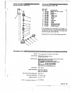
Valves
NOTE:
2. Carefully pull the packing retainer (212)from the
To replace valves, order
kit
part no. 801
-
472.
manifold. Examine the O-ring (213)and replace
it
if
it
is cut or damaged.
..
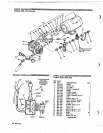
1.
Remove the hex plug (205) from the manifold
3. Remove the v-packing (210) and head ring (209).
Pull out the intermediate retainer ring (211).
Remove the v-packing
(21
0)
and head ring (209).
(206) using
an
M30 wrench.
2. Examine the O-ring (204) under the plug and
replace
it
if
it
is cut or distorted,
4.
Inspect all pans and replace as necessary.
3. Remove the valve assembly(203)from thecavity;
5. Thoroughly clean the packing cavities and
the assembly may come apart. examine.
4.
Install a new valve (203). Install the O-ring (204) 6. Lightly grease the packing cavities
and
then
and plug (205) and torque to 75 ft-lb (10.3 Nm).
ring (209). v-packing (210). intermediate ring
replace the packings
in
the following order: head
NOTE:
Retorque the plug after 5 hours of
(21 1). head ring (209),packing(210). andpacking
operation.
retainer (212). with the O-ring (213)installedinto
the retainer groove.
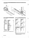
Pumping Section
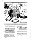
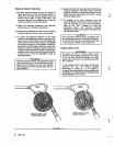
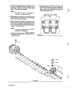
1. Remove the six Allen head cap screws (20l)and order and facing the correct direction. See
lockwasher(202)from the manifold(206)usinga
M6 Allen wrench.
Figure
4.
Improperly installed pans will cause a
malfunction.
2. Carefully separate the manifold from the
crankcase.
It
may be necessry to tapthe manifold
lightly with
a
rubber mallet.
the manifold properly aligned with the ceramic
plungers when removing
it.
3.
Carefully examine each plunger (219) and
replace
it
if there is any scoring.
Servicing
The
V-Packings
NOTE:
To replace just the v-packings, use kit
entire pump.
pan no. 801 -662 which will service the
To replace the v-packings. rings and
retainers, order
two
of kit pan
no.
801-
664 to service the entire pump.
1.
If
the manifold is not already removed, follow
Steps
1
and 2 of pumping section.
7. Reassemble the manifold as instructed
in
Steps 7
and 8 of Servicing The Plungers.
Servicing
The
Plungers
NOTE:
available to service all
the plungers.
Plunger repair kit, pan
no.
801-474, is
1. Loosen the plunger retaining screws (21 5). 5 to 6
turns, using
an
M10
wrench. Push the plunger
plunger and retaining screw.
(219) toward the crankcase to separate the
2. Remove the screw (215) from'the plunger and
examine the O-ring (217). backup ring (218) and
these pans, if necessary, using kit part no. 801
-
copper bearing/gasket washer (216). Replace
474.
3.
Remove the plunger (219) andflinger (220)from
parts as necessary.
the plunger shaft. Clean, examine and replace
802-776
9
,
.
,
. .
.
.
.. . ..
,.
..
,