


Reassembly
1.
Examine inlet valve surface and reverse if damaged.
(Both sides are lap surfaces.)
2.
Examine piston assembly for clean inlet surface.
If
damaged, replace and lubricate.
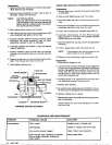
NOTE: CUP INSTALLATION
Wipe
cup inserter lightly
with
oil. Slip backup
ring onto piston. Force cup over inserter and
tion causes premature failure.
square
with
all surfaces. Faulty cup installa-
3.
Next replace piston spacer and retainer.
4.
Slip washer onto rod, screw on
nut
and torque to
60
in-lb.
ALWAYS USE NEW COTTER PIN.
5.
Examine cylinder wallsfor scoring oretching.These
conditions
will
cause premature wear of piston
assemblies. Replace if worn or damaged.
6.
Lubricate cylinder and replace O-rings and backup
rings (if defective).
7.
Position cylinders
in
their original order into manifold
chambers and carefully slip over rod ends onto the
pump.
8.
Replace flange nuts on studs and hand tighten both
sides. Then torque each side to
125
in-lb.
9.
Hand tighten locking nuts.
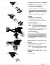
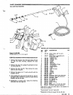
PUMPING SECTION CUTAWAY
SEALS AND
SLEEVES
Disassembly
1.
Remove discharge manifold and piston assemblies
as described.
2.
Remove both
(ME)
locking nuts from studs
3.
With soft mallet, tap inlet manifold loosefromcrank-
case.
4.
Place inlet manifold on pair of clearance blocks
with
crankcase side down, and drive out seals.
5.
Invert inlet manifold
with
CRANKCASE
SIDE
UP.
6.
Lubricate circumference of new Prrrrrm-A-Lube
seals, position
in
manifold with GARTER
SPRING
DOWN and drive into place.
7.
Examine sleeves for scoring or other damage before'
8.
If worn, grasp sleeve
with
pliers and pull off.
removing.
NOTE: This procedure will marthesleeveso use
only if sleeve is
to
be replaced.
9.
Remove O-ring and backup rings from piston rod.
Reassembly
1.
Place barrier slinger on rod
2.
Lubricate new o:rings and backup rings. Install first
O-ring
in
the O-ring groove on the piston rod. Position
backup ring against the shoulder
in
front of the first
O-ring, then the second O-ring. Be careful to avoid
damaging the O-rings when slipping them over the
piston rod threaded ends.
3.
Immerse sleeve
in
oil, carefully twist and push onto
rod. (Machined counter bore end first.)
4.
Replace seal retainers.
5.
Be careful when replacing inlet manifold,
so
the
in-
let seals are not damaged by the threaded rod ends.
6.
Replace locking nuts on studs.
7.
Reassemble piston assemblies and discharge mani-
fold as described.
case servicing.
Consult factory for your local distributor for crank-
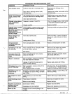
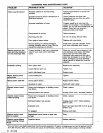
DIAGNOSIS AND MAINTENANCE
PROBLEM
Low
pressure
PROBABLE CAUSE
Clean. Check more frequently.
Inlet suction strainer clogged.
Tighten or replace; use correct belt.
Belt slippage.
Replace nozzle, of proper size.
Worn nozzle.
SOLUTION
fluid or severe cavitation. Inadequate
Worn plunger cups. Abrasives
in
pumped
Install proper filter.
water supply.
..