


Section 2.3
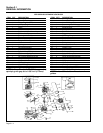
PISTON, RINGS, CONNECTING ROD
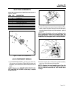
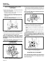
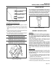
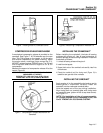
Figure 4. Piston Minor Diameter
PISTON MINOR DIAMETER GV-220)
Design DIAMETER: 2.747-2.748 inch (69.789-69.809mm)
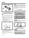
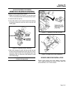
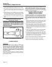
Figure 5. Piston Major Diameter
PISTON MAJOR DIAMETER GV-220)
Design DIAMETER: 2.753-2.754 inch (69.939-69.959mm)
NOTE: Always apply engine oil to wrist pin and its
bores during Installation. Wrist pin fit is very
close.
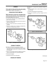
4. Check Wrist Pin for Wear: Measure the outside diameter of the
wrist pin. Also measure the inside diameter of the wrist pin
bore in the piston and in the connecting rod. Also check wrist
pin length. Replace any component that Is worn excessively.
WRIST PIN OUTSIDE DIAMETER (GV-220)
DESIGN DIAMETER: 0.708-0.709 inch (17.989-18.000mm)
WEAR LIMIT: 0.707 inch (17.969mm) Minimum
WRIST PIN LENGTH (GV-220)
DESIGN LENGTH: 2.196-2.213 inch (55.8-56.2mm)
WEAR LIMIT: 2.193 inch (55.7mm) Minimum
WRIST PIN BORE IN PISTON (GV-220)
DESIGN DIAMETER: 0.708-0.709 inch (18.000-18.011mm)
WEAR LIMIT: 0.710 inch (18.026mm) Maximum
CONNECTING ROD SMALL END I.D. (GV-220)
DESIGN DIAMETER: 0.709-0.710 inch (18.02-18.03mm
WEAR LIMIT: 0.711 inch (18.05mm) Maximum
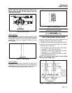
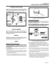
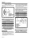
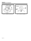
5. Ring to Groove Side Clearance:- Clean carbon from piston ring
grooves as. Install new rings. Use a feeler gauge to measure the
side clearance between the rings and ring grooves. If ring-to-
groove side clearance exceeds the stated limits, replace the pis-
ton.
RING TO GROOVE SIDE CLEARANCE (GV-220)
0.0004-0.0014 inch (0.012-0.034mm)
Figure 6. Ring to Groove Side Clearance
PISTON RINGS
GENERAL:
The following rules pertaining to piston rings must
always be complied with:
• Always replace piston rings in sets.
• When removing rings, use a ring expander to pre-
vent breakage. Do not spread the rings too far or
they will break.
• When installing the piston into the cylinder, use a
ring compressor. This wilt prevent ring breakage
and/or cylinder damage.
• When installing new rings, deglaze the cylinder wall
with a commercially available deglazing tool.
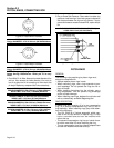
RING DESCRIPTION:
A piston ring SET consists of (a) a top compression
ring, (b) a second compression ring, and (c) an oil
ring assembly. When installing rings, pay close atten-
tion to the following:
• The OIL RING is a 3-piece assembly which con-
sists of two oil rails and an oil spacer ring. Oil rails
have a rounded face and can be installed with
either side up.
• The second compression ring has an inside cham-
fer which must face UP when installing the ring.
• The top compression ring has a barrel-shaped face
and can be installed with either side up.
Page 2.3-2