


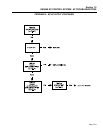


Section 7.2
ENGINE DC CONTROL SYSTEM / AC TROUBLESHOOTING
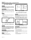
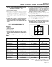
TEST 29 - 9-PIN WIRE HARNESS/ 2-PIN WIRE
HARNESS CONTINUITY TEST
1) Set VOM to measure Resistance.
2. Measure from pin location #1 on one end of the 9-wire harness
to pin location #1 on the opposite end of the harness. A read-
ing of “Continuity” should be measured. Repeat procedure for
each pin position on both the 9-wire and 2-wire harnesses. If
an open condition is detected, replace the defective harness as
necessary.
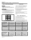
3. If needed, check for continuity on the A6060 circuit board wire
harness in the control panel. This connectioon is at location J1
on the circuit board. Follow the same procedure as steps 1 and
2 above.
TEST 30
-
9-WIRE HARNESS SIGNALS TEST
ASSUMPTION:
• Engine runs
• Inverter not connected
TEST PROCEDURE:
1. Disconnect the 2-wire and 9-wire cables from the inverter.
Disconnect the Red-Black-Blue-Green DC Link wires from the
inverter.
Note: Cap the DC Link wires with a wire nut for
safety.
2. On units with A6060 circuit board revision “D” or higher soft-
ware, jump pin #6 to pin #7 on the 9-wire cable previously
removed from the inverter. The 9-wire cable should be con-
nected to the 9-wire socket on the generator control panel. This
will enable the generator to run with CB1 turned ON.
3. Turn CB1 to ON position. Start generator. The engine should
run at approximately 3300rpm.
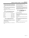
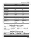
4. Set a DVOM to DC volts. Measure from the free end of the 9-
Wire harness according to the chart below. Connect the nega-
tive and positive test leads as indicated in the chart.
(Note: Fluke 87 true RMS meter used in test.)
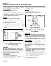
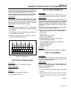
5. Set a DVOM to AC volts. Measure the the free end of the 9-
Wire harness according to the chart below. Connect the nega-
tive and positive test leads as indicated in the chart.
Figure 10 Free End of 9-Wire Harness
Page 7.2-17
Test With DVOM
Set At DC Volts Connect negative lead to: Connect positive lead to: Reading should be:
Inverter Signals Ground Pin 5 (0 v) Pin 2 (En/Com) < 0.10 vdc
Inverter Signal Pin 2 (En/Com) Pin 1 (PWM1) 2.5 v ± 0.15 vdc
Inverter Signal Pin 2 (En/Com) Pin 3 (PWM2) 2.5 v ± 0.15 vdc
Temperature Voltage Pin 5 (0 v) Pin 6 (TEMP) 5.0 v ± 0.1 vdc
Inverter Fan Voltage Pin 5 (0 v) Pin 4 (Wire #14) 12 v ± 1.0 vdc
Shield Wire
Test for Ground Pin 8 (SHIELD) Pin 4 (Wire #14) 12 v ± 1.0 vdc
Test With DVOM
Set At AC Volts Connect negative lead to: Connect positive lead to: Reading should be:
Inverter Signal Pin 2 (En/Com) Pin 1 (PWM1) 2.5 v ± 2.0 vac*
Inverter Signal Pin 2 (En/Com) Pin 3 (PWM2) 2.5 v ± 2.0 vac*
* Tolerance is large because readings will vary,
depending on type of meter used.