


Section 1.1
GENERATOR FUNDAMENTALS
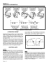
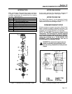
CAPACITIVE REACTANCE:
This condition occurs when current leads voltage
(Figure 9). It might be thought of as the ability to oppose
change in voltage. Capacitance exists in a circuit when
certain devices are ~a) capable of storing electrical
charges as voltage increases and (b) discharging these
stored charges when the voltage decreases.
Figure 9. Capacitive Reactance
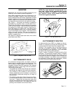
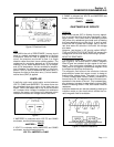
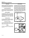
WHAT IS AN "IMPACT PLUS" UNIT?:
The Impact Plus is a computer controlled generator
that uses an inverter to create a superior sine wave
and maintain a steady frequency. These units are dif-
ferent from conventional generators in that the perfor-
mance of the engine and AC generator are more
accurately matched over a wide range of power
needs. The Impact Plus computer controlled genera-
tor provides greater efficiency of both the engine and
the generator while maintaining electrical output with-
in an acceptable voltage range. The frequency is con-
trolled by the inverter and is maintained at a steady
60 Hz signal throughout the load range.
Computer controlled generator units have the ability
to operate the engine over a wide range of speeds,
while conventional generators will deliver correct AC
frequency and voltage only at a fixed rpm.
Unlike conventional AC generators, the Impact Plus
unit can match engine speed to load requirements.
This provides several advantages, as follows:
• Smaller engines can be used to produce more
power than on a conventional generator, since it
can be allowed to run at a higher speed.
• When the load is reduced, the engine can run at
slower than the usual speeds. This improves fuel
economy and reduces engine noise.
• The Impact Plus unit can be operated closer to its
peak power point at all times, because output volt-
age and current are functions of engine speed. This
allows for a much more compact generator design.
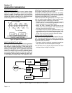
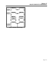
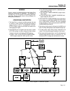
IMPACT PLUS SYSTEM OVERVIEW:
Figure 10 is a block diagram of the Impact Plus sys-
tem. The major elements of the system are represent-
ed in the diagram. Operation of the system may be
described briefly as follows:
1. The engine is directly coupled to a permanent magnet type
Rotor, so the Rotor runs at the same speed as the engine.
2. As the Rotor turns, its magnetic field cuts across the Stator
windings to induce a voltage into the Stator.
Page 1.1-4
Figure 10. Block Diagram of the Impact 36 Plus System