


Section 7.2
ENGINE DC CONTROL SYSTEM / AC TROUBLESHOOTING
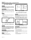
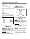
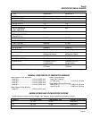
ENGINE COMPRESSION PRESSURE
NOMINAL PRESSURE: 60 psi
MINIMUM ALLOWABLE: 55 psi
NOTE: Full compression pressure cannot be
obtained at cranking speeds, due to the action of
a compression release mechanism.
RESULTS:
If compression is poor, look for one or more of the fol-
lowing possible causes:
1. Loose cylinder head bolts.
2. Failed cylinder head gasket.
3. Burned valves or valve seals.
4. Insufficient valve clearance.
5. Warped cylinder head.
6. Warped valve stem.
7. Worn or broken piston ring(s).
8. Worn or damaged cylinder bore.
9. Broken connecting rod.
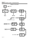
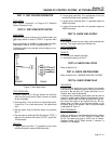
TEST 26- TEST OIL PRESSURE SWITCH
DISCUSSION:
See Section 6.5, "ENGINE SHUTDOWN FEATURES.”
TEST PROCEDURE:
See Section 6.5.
If necessary, connect an external oil pressure gauge
to the oil pressure switch port.
RESULTS:
1. Replace oil pressure switch if it is defective or repair Wire 85
circuit as necessary.
2. If oil pressure is actually low as indicated by the external
gauge, see Section 5.1, "ENGINE OIL SYSTEM".
3. If oil pressure is good and oil pressure switch is good, go to
Test 27.
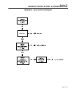
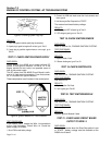
TEST 27- TEST OIL TEMPERATURE SWITCH
DISCUSSION:
See Section 6.5, "ENGINE SHUTDOWN FEATURES.”
TEST PROCEDURE:
See Section 6.5.
RESULTS:
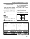
NOTE: On new units model 940-1 serial number
3128481 and higher and model 941-1 serial num-
ber 3127103 and higher the generator will shut-
down if the 9-wire cable is disconnected. The
A6060 circuit board has updated software to
enable this shutdown and is labeled “D” or higher
on the circuit board. In order to perform the run-
ning diagnostic tests you must jump pin #6 to pin
#7 this will enable the unit to continue to run with
the 9-wire harness disconnected.
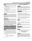
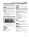
TEST 28 - DC LINK VOLTAGE TEST
1. Disconnect the 2-wire and 9-wire cables from the inverter.
Disconnect the Red-Black-Blue-Green DC Link wires from the
inverter.
Note: Cap the DC Link wires with a wire nut for
safety.
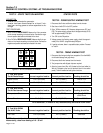
2. On units with A6060 circuit board revision “D” or higher soft-
ware, jump pin #6 to pin #7 on the 9-wire cable previously
removed from the inverter. The 9-wire cable should be con-
nected to the 9-wire socket on the generator control panel. This
will enable the generator to run with CB1 turned ON.
3. Turn CB1 to ON position. Start generator. The engine should
run at approximately 3300rpm.
4. Set VOM to DC. Measure DC Link voltage between the Red
and Blue wires. DC voltage should be approximately 375 VDC.
Measure DC Link voltage Between the Red and Black, and
between the Blue and Black wires. These two readings should
be approximately 187 VDC.
Page 7.2-16