


Section 7.2
ENGINE DC CONTROL SYSTEM / AC TROUBLESHOOTING
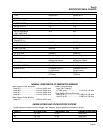
TEST 31 - STATIC TESTS ON INVERTER
ASSUMPTION:
• Inverter not connected to generator.
• Inverter has been disconnected for at least 5 min-
utes from running genset to allow capacitors to dis-
charge.
TEST PROCEDURE:
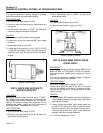
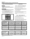
1. Set a DVOM to DIODE RANGE. Measure the 9-pin connector
on the inverter according to the chart below. Connect the nega-
tive and positive test leads as indicated in the chart.
2. Set a DVOM to RESISTANCE RANGE. Measure the 9-pin con-
nector on the inverter according to the chart below. Connect the
negative and positive test leads as indicated in the chart.
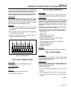
Figure 11. 9-Pin Connector on Inverter
STATOR TESTS
TEST 32 - POWER SUPPLY WINDING TEST
1. Disconnect the 2-wire and 9-wire cables from the inverter.
2. Start the unit with CB1 in the OFF position.
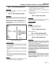
3. Set a VOM to measure AC. Measure voltage across PS1 and
PS2. The power supply voltage should be approximately 25-30
VAC at approximately 2700 rpm.
4. Turn CB1 to the ON position.
5. Voltage across the floating power supply should be approxi-
mately 30 to 34VAC at approximately 3400rpm.
6. If results are lower, there is a possible stator problem. Proceed
to Test 34.
TEST 33 - TIMING WINDING TEST
1. Disconnect the timing winding from receptacle J5 on the A6060
circuit board (orange and grey wires).
2. Disconnect the 9-wire harness from the inverter.
3. Two jumper wires with alligator clips are required.
4. Attach a jumper from Wire #15 (located at the fuse holder) to
Wire #14 (located at the four tab terminal block in the control
panel). This will enable fuel and ignition functions.
Page 7.2-18
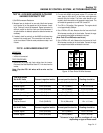
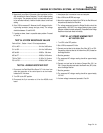
*NTC thermistor; if inverter is hot, resistance may be several kOhm lower.
1. Test With DVOM
Set At Diode Range Connect negative lead to: Connect positive lead to: Reading should be:
Signal Circuit Pin 2 (En/Com) Pin 1 (PWM1) 1.25 to 1.5 v
Signal Circuit Pin 2 (En/Com) Pin 3 (PWM2) 1.25 to 1.5 v
2. Test With DVOM
Set At Resistance Range Connect negative lead to: Connect positive lead to: Reading should be:
Temperature Circuit Pin 5 (0 V) Pin 6 (TEMP) 10 kOhm @ 25°C*
±500 Ohms
Sense Circuit Pin 5 (0 V) Pin 7 (SENSE) 20 kOhm ± 200 Ohm
3. Test With DVOM
Set At AC Volts Connect negative lead to: Connect positive lead to: Reading should be:
Fan Test Pin 2 (En/Com) Pin 1 (PWM1) See Note
NOTE: Use a ballpoint pen or small screwdriver to spin the blades of the inverter-cooling fan.
Momentarily, observe a reading of 10 - 30 mV.