


Activation and Startup
12 Owner’s Manual for Stationary Diesel Generators
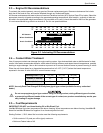
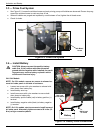
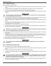
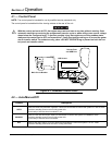
3.3 — Prime Fuel System
1. See Figure 3-3. Loosen the air bleed screw and work priming pump until bubbles are observed. Place a shop rag
around the air bleed screw to catch any loss of fuel.
2. When all bubbles are purged and replaced by a solid stream of fuel, tighten the air bleed screw.
3. Check for leaks.
Figure 3-3. Prime Fuel System
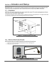
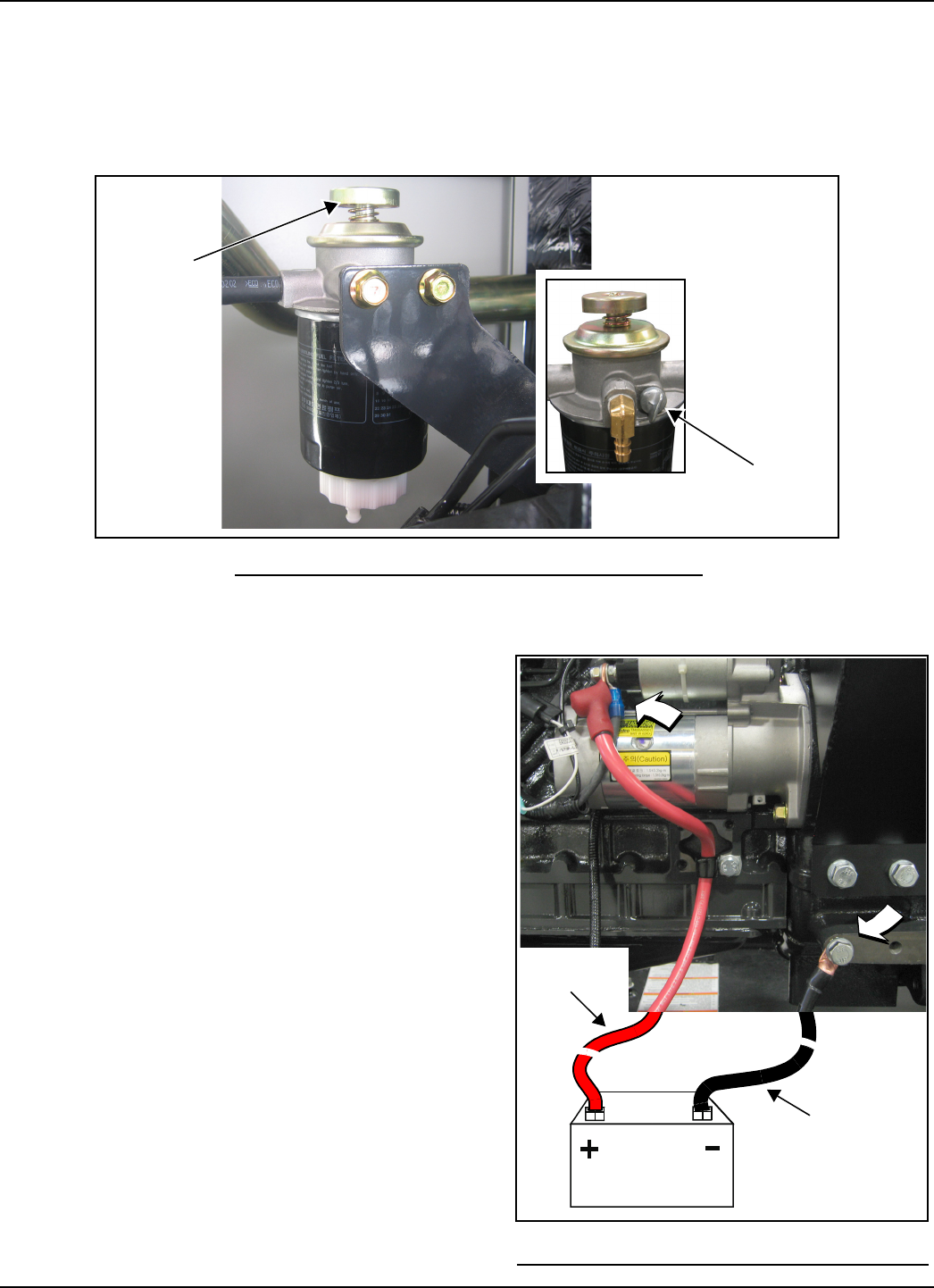
3.4 — Install Battery
CAUTION: Always connect the positive battery
cable first. If the positive cable should contact
ground with the negative cable installed, the result-
ing sparks may cause a battery explosion which
could result in serious injury.
2.4L/3.4L Models
NOTE: On 2.3L models, remove ten screws to release lou-
vered air intake panel on left side of enclosure.
1. Loosen two screws with nylon washers to release hold-
down clamp from battery tray.
2. Install battery onto tray.
3. Install two screws with nylon washers to secure hold-
down clamp to battery tray.
4. Install battery positive cable (red) to battery positive (+)
terminal.
5. Install battery negative cable (black) to battery negative
(-) terminal.
NOTE: On 2.3L models, start ten screws to install louvered
air intake panel. Alternately tighten screws to 90 in-lbs (10
N-m) using a crosswise pattern.
Priming
Pump
Air Bleed
Screw
$
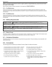
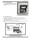
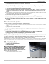
Figure 3-4. Battery Cable Connections
Battery
Red Lead
From Starter
Black Lead
To Frame