


6 Generac
®
Power Systems, Inc.
With LP gas, use only the vapor withdrawal system.
This type of system uses the vapors formed above the liq-
uid fuel in the storage tank.
The engine has been fitted with a fuel carburetion sys-
tem that meets the specifications of the 1997 California
Air Resources Board for tamper-proof dual fuel sys-
tems. The unit will run on natural gas or LP gas, but it
has been factory set to run on natural gas. Should the
primary fuel need to be changed to LP gas, the fuel sys-
tem needs to be reconfigured. See Section 1.6.4 (Page
6) for instructions on reconfiguration of the fuel system.
Recommended fuels should have a Btu content of at
least 1,000 Btus per cubic foot for natural gas; or at
least 2,520 Btus per cubic foot for LP gas. Ask your fuel
supplier for the Btu content of your fuel.
Fuel pressure for both natural gas and liquid propane
(LP) vapor set ups MUST be 11 inches to 14 inches of
water column (0.6 psi) at all load ranges.
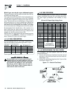
1.6.2 FUEL CONSUMPTION
See the following chart for fuel supply requirements at
half and full load for both natural gas and LP vapor.
*Natural gas is in cubic feet per hour.
**LP is in gallons per hour/cubic feet per hour.
Gaseous fuels such as natural gas and liquid
propane (LP) gas are highly explosive. Even the
slightest spark can ignite such fuels and cause
an explosion. No leakage of fuel is permitted.
Natural gas, which is lighter than air, tends to
collect in high areas. LP gas is heavier than air
and tends to settle in low areas.
1.6.3 FUEL PIPE SIZING
See the following chart for proper sizing of fuel supply
piping. Insufficient fuel pipe size can cause hard start-
ing, poor engine performance and inability to carry
load.
NG and LP Vapor Pipe Sizing Chart:
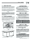
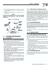
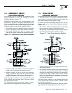
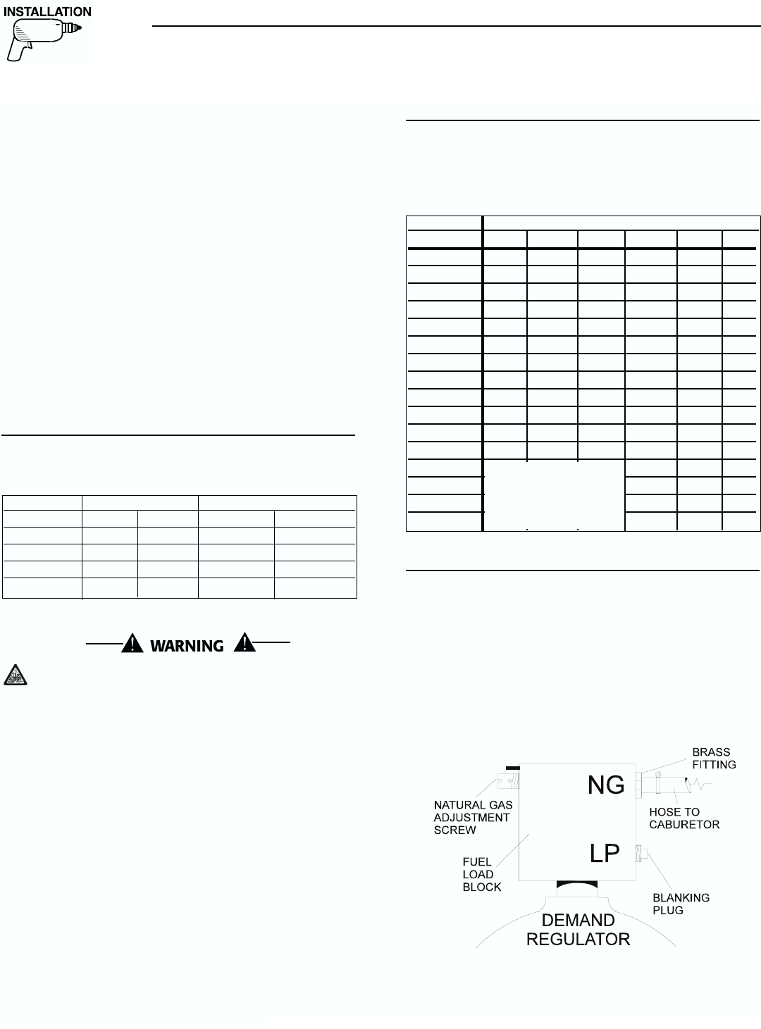
1.6.4 RECONFIGURING THE FUEL SYSTEM
To reconfigure the fuel system from NG to LP,
follow these steps:
1. Remove the carburetor fuel hose from the natural
gas port of the fuel load block and the brass fit-
ting (Figure 1.2).
2. Remove the blanking plug from the LP port of the
load block (Figure 1.2).
Figure 1.2 – Natural Gas Setup`
◆
◆
◆
Section 1 — Installation
Guardian Air-cooled Generators
Model # Nat. Gas (*) LP Vapor (**)
1/2 Load Full Load 1/2 Load Full Load
6 kW 74.1 105.3 0.86/31.30 1.08/39.30
8 kW 79.7 140.0 1.07/38.94 1.56/56.77
10 kW 100.8 177.9 1.16/42.21 2.15/78.24
Sound Attn. 84.6 126.6 1.06/38.57 1.7/61.86
Length of Pipe Iron Pipe Size (IPS Inches)
½" ¾" 1" 1 ¼" 1 ½" 2"
15' 76 172 345 750 1,220 2,480
30' 52 120 241 535 850 1,780
45' 43 99 199 435 700 1,475
60' 38 86 173 380 610 1,290
75' 77 155 345 545 1,120
90' 70 141 310 490 1,000
105 65 131 285 450 920
120 120 270 420 860
150 109 242 380 780
180 100 225 350 720
210 92 205 320 660
240 190 300 620
270 178 285 580
300 170 270 545
450 140 226 450
600 119 192 390
Consumption in
Cubic Feet Per Hour