


Generac
®
Power Systems, Inc. 15
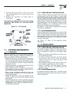
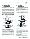
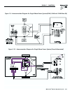
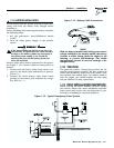
1.14 ADAPTING THREE-PHASE
TRANSFER SWITCH
The generator you are installing may include a
prepackaged transfer switch configured for three-
phase loads. If you want to adapt this kind of transfer
switch for single-phase loads, proceed as follows:
1. Discard the three-phase power monitor (PM)
found inside the enclosure. You will not use it
with a single-phase system.
2. Locate the eight-pin octal relay socket in the lower
left corner of the transfer switch enclosure.
3. Move Wire N1A from Terminal 8 to Terminal 1 by
cutting the lug off of N1A , stripping wire 5/16"
from end, and inserting the wire under screw of
Terminal 1.
NOTE:
Moving N1A from Terminal 8 to Terminal 1 takes
the three-phase voltage monitor out of the sensing
circuit. Now, the control circuit board in the con-
trol module assembly (CMA) senses utility voltage.
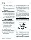
4. Now, connect the control wires as follows:
• Connect Utility Supply to lugs N1 and N2.
• Connect the Customer Load lugs T1 and T2.
• Connect the Standby Supply to lugs E1 and E2.
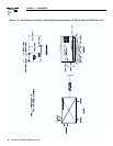
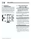
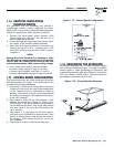
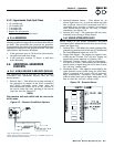
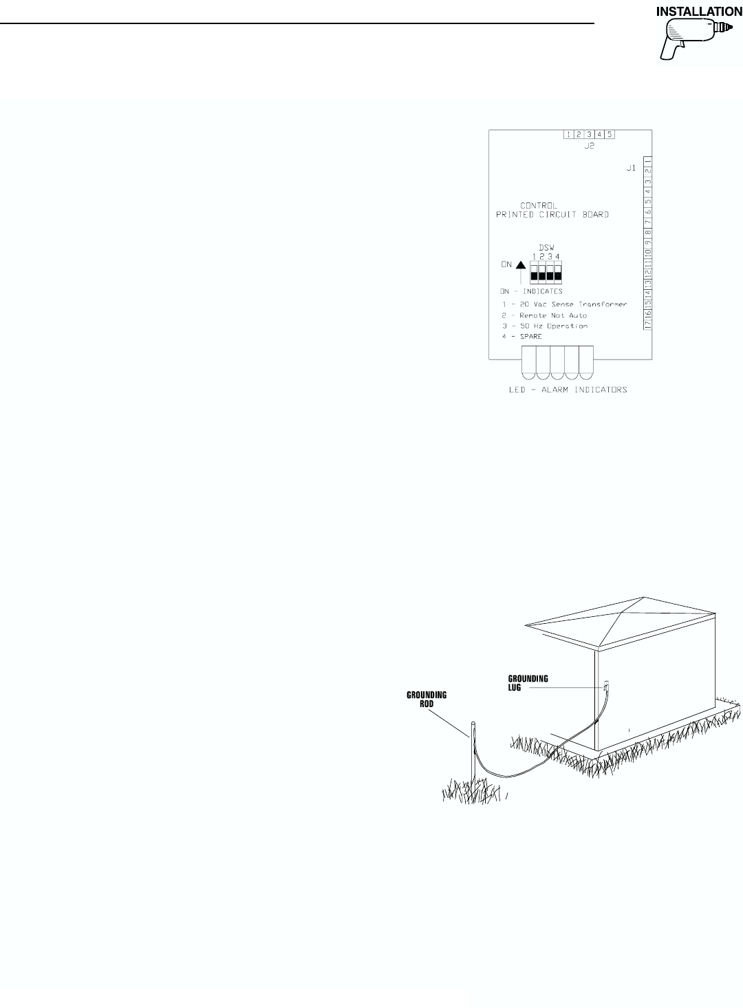
1.15 CONTROL BOARD CONFIGURATION
The control board for the 6 kW, 8 kW and 10 kw has
four dip switches (see Figure 1.12), which may be set
up differently during installation.
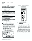
1. Dip switch 1: When in the ON position, the board
requires 20 Vac from the step down transformer
to the control board to determine if utility is
present. This switch is factory preset and should
not need to be changed. This switch should be set
in the OFF position.
2. Dip switch 2: When in the ON position, it will
disable the automatic starting of these units.
This should be set when utility is not present at
the installation location. This is the only switch
that may need to be set to the ON position for
these models.
3. Dip switch 3: It will allow for 50 Hertz opera-
tion and is not applicable to these models. This
switch is factory preset and should not need to
be changed. This switch should be set in the
OFF position.
4. Dip switch 4: It has no function at this time.
Figure 1.12 – Control Board Configuration
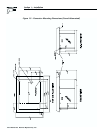
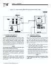
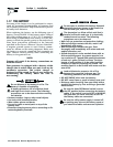
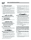
1.16 GROUNDING THE GENERATOR
Generally, connecting a No. 12 AWG stranded copper
wire to the grounding lug (Figure 1.13) and to an earth-
driven copper or brass grounding rod (electrode) will
adequately ground the generator. However, local codes
may vary widely. Consult with a local electrician for
grounding requirements in your area.
Figure 1.13 – Grounding the Generator
Section 1 — Installation
Guardian Air-cooled Generators