


20 Generac
®
Power Systems, Inc.
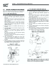
6. To crank and start the engine, set the
Auto/Off/Manual switch to MANUAL.
7. Let the engine stabilize and warm up for a few
minutes.
8. Set the generator’s main circuit breaker to its ON
(or closed) position. The standby power source
now powers the loads.
2.4.2 TRANSFER BACK TO UTILITY
POWER SOURCE
When utility power has been restored, you will want
to transfer back to that source and shut down the
generator. This can be accomplished as follows:
1. Set the generator’s main circuit breaker to its
OFF (or open) position.
2. Let the engine run for a minute or two at no-load
to stabilize the internal temperatures.
3. Set the generator’s Auto/Off/Manual switch to
its OFF (or open) position. The engine should
shut down.
4. Check that utility power supply to the transfer
switch is turned OFF.
Do not attempt to activate the transfer switch
manually until all power voltage supplies
to the switch have been positively turned off.
Failure to turn off all power voltage supplies
may result in extremely hazardous and possibly
fatal electrical shock.
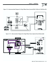
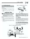
5. Use the manual transfer handle inside the trans-
fer switch to move the main contacts back to their
“Utility” position, i.e., loads connected to the util-
ity power source (Figure 2.3, Page 19).
6. Turn ON the utility power supply to the transfer
switch using the means provided.
7. Set the system to automatic operation as
outlined in “Automatic Transfer Operation,”
Section 2.2 (Page 18).
2.5 PROTECTION SYSTEMS
Unlike an automobile engine, the generator may have
to run for long periods of time with no operator pres-
ent to monitor engine conditions. For that reason, the
engine is equipped with the following systems that
protect it against potentially damaging conditions:
1. Low Oil Pressure Sensor
2. High Temperature Sensor
3. Overcrank
4. Overspeed
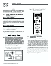
On sound attenuated models, there are LED read-
outs on the control panel to notify you that one of
these faults has occurred. There is also a “System
Set” LED that is lit when all of the following condi-
tions are true:
1. The Auto/Off/Manual switch is set to the AUTO
position.
2. The “Not In Auto” dip switch is set to the OFF
position on the control board.
3. No alarms are present.
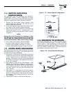
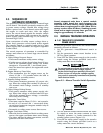
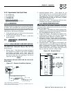
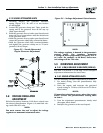
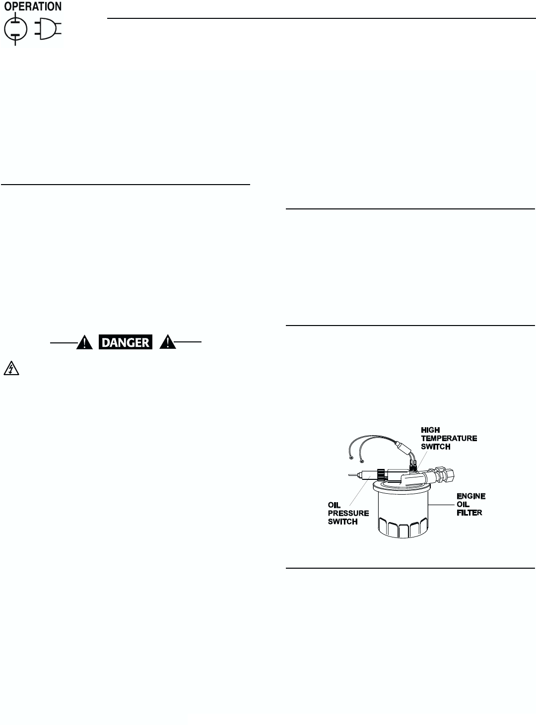
2.5.1 LOW OIL PRESSURE SWITCH
This switch (Figure 2.4) has normally closed contacts
that are held open by engine oil pressure during
cranking and operating. Should oil pressure drop
below the 8 psi range, switch contacts close, and the
engine shuts down. The unit should not
be restarted until oil is added, and the
Auto/Off/Manual switch must be turned to OFF and
then back to AUTO.
2.5.2 HIGH TEMPERATURE SWITCH
This switch’s (Figure 2.4) contacts close if the tem-
perature should exceed approximately 140º C (284º
F), initiating an engine shutdown. Your generator will
automatically restart and the LED will reset once the
temperature has returned to a safe operating level.
Figure 2.4 – Low Oil Pressure and
High Temperature Switches
2.5.3 OVERCRANK
This feature prevents the generator from damaging itself
when it continually attempts to start and another prob-
lem, such as no fuel supply, prevents it from starting.
The unit will crank and rest for a preset time limit.
Then, it will stop cranking, and the LED will light indi-
cating an overcrank failure. The Auto/ Off/Manual switch
will need to be set to OFF and then back to AUTO to
reset the generator control board.
NOTE:
If the fault is not repaired, the overcrank feature
will continue to activate.
◆
◆
◆
◆
Section 2 — Operation
Guardian Air-cooled Generators