


12 Generac
®
Power Systems, Inc.
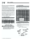
1.10 GENERATOR AC
CONNECTION SYSTEM
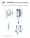
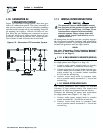
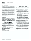
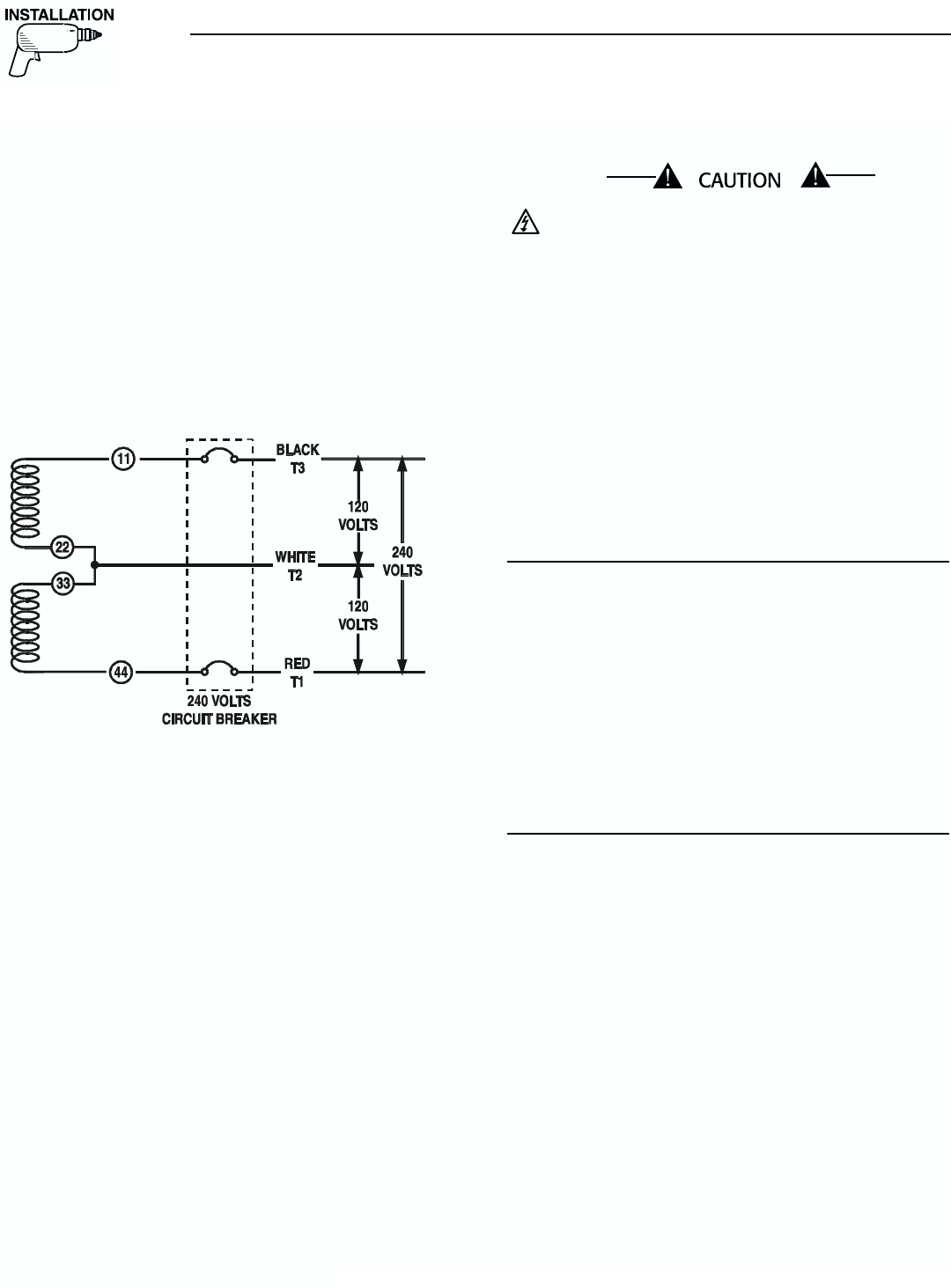
Figure 1.8 represents a single-phase, three-wire gen-
erator AC connection system. The stator assembly in
this system consists of a pair of stationary windings
with two leads brought out of each winding. Each sin-
gle winding can supply a 120-volt, 60-Hertz AC out-
put. When the two windings are connected in series,
a 240-volt, 60-Hertz AC output results. Stator AC out-
put leads 11 and 44 are the two “hot” leads; the junc-
tion of leads 22 and 33 forms the neutral lead.
Figure 1.8 – Generator AC Connection System
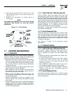
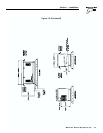
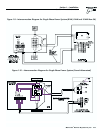
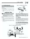
1.11 WIRING INTERCONNECTIONS
This generator uses an UNGROUNDED neutral
line consisting of the junction of stator leads 22
and 33. Figure 1.9 and Figure 1.10 (Page 13) are
interconnection diagrams of home standby
electrical systems. Power voltage leads and
transfer switch “signal” leads must be run in
separate conduit.
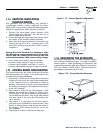
All wiring must be the proper size, properly support-
ed, of approved insulative qualities, and protected by
NEC approved conduit. Use a length of flexible conduit
between the generator and any rigid conduit.
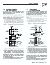
NOTE:
See also “Emergency Circuit Isolation Method,”
Section 1.8, and “Total Circuit Isolation Method,”
Section 1.9, on Page 11.
1.11.1 6 KW, 8 KW AND 10 KW UNITS (NON-SA)
Complete the following AC power lead connections
for single-phase units (Figure 1.9, Page 13):
1. Connect utility power supply leads to transfer
switch terminals N1, N2 and the neutral lug.
2. Connect generator AC output leads from the gen-
erator’s main circuit breaker (CB1) and the gen-
erator neutral lug to transfer switch terminals
E1, E2 and the neutral lug.
3. Connect circuit load leads to customer load,
and to transfer switch terminals T1, T2 and the
neutral lug.
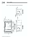
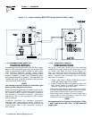
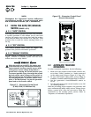
1.11.2 SOUND ATTENUATED UNITS
The sound attenuated unit utilizes an internal
100-amp “V”-type transfer switch. The control and
generator AC wires are prewired from the factory.
Complete the following AC power lead connections
for single-phase units (Figure 1.10, Page 13):
1. Connect utility power supply leads to transfer
switch terminals N1, N2 and the neutral lug.
2. Connect circuit load leads to customer load,
and to transfer switch terminals T1, T2 and the
neutral lug.
◆
◆
Section 1 — Installation
Guardian Air-cooled Generators