


Generac
®
Power Systems, Inc. 23
Do not attempt manual transfer switch
operation until all power voltage supplies to
the transfer switch have been positively turned
off. Failure to turn off all power voltage
supplies will result in extremely hazardous
and possibly fatal electrical shock.
4. Manually set the transfer switch to the STANDBY
position, i.e., load terminals connected to the
generator's E1/E2 terminals. The transfer switch
operating lever should be down.
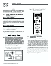
5. Set the generator's Auto/Off/Manual switch to
MANUAL. The engine should crank and start
immediately.
6. Let the engine stabilize and warm up for a few
minutes.
7. Set the generator’s main circuit breaker to its ON
(or closed) position. Loads are now powered by
the standby generator.
8. Turn ON electrical loads. Apply an electrical load
equal to the full rated wattage/amperage capacity
of the installed generator.
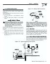
9. Connect an accurate AC frequency meter across
terminal lugs E1 and E2. Voltage should be
greater than 230 volts; frequency should be
greater than 58 Hertz.
10. Let the generator run at full rated load for 20-30
minutes. Listen for unusual noises, vibration or
other indications of abnormal operation. Check
for oil leaks, evidence of overheating, etc.
11. When testing under load is complete, turn OFF
electrical loads.
12. Set the generator's main circuit breakers to their
OFF (or open) positions.
13. Let the engine run at no-load for a few minutes.
14. Set the Auto/Off/Manual switch to OFF. The
engine should shut down.
3.5 CHECKING AUTOMATIC
OPERATION
To check the system for proper automatic operation,
proceed as follows:
1. Check that the Auto/Off/Manual switch is set
to OFF.
2. Manually set the transfer switch to the UTILITY
position, i.e., load terminals connected to the util-
ity power source side.
3. Turn ON the utility power supply to the transfer
switch, using the means provided (such as a util-
ity main line circuit breaker).
4. Set the Auto/Off/Manual switch to AUTO. The sys-
tem is now ready for automatic operation.
5. Turn OFF the utility power supply to the transfer
switch.
With the Auto/Off/Manual switch at AUTO, the engine
should crank and start when the utility source power
is turned OFF. After starting, the transfer switch
should connect load circuits to the standby side. Let
the system go through its entire automatic sequence
of operation.
With the generator running and loads powered by
generator AC output, turn ON the utility power sup-
ply to the transfer switch. The following should
occur:
• After about six seconds, the switch should transfer
loads back to the utility power source.
• About one minute after retransfer, the engine
should shut down.
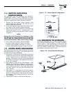
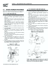
3.6 ADJUSTING THE LOAD BLOCK
When the natural gas system is being used, the load
block is fitted with an adjustment screw that has
been calibrated to provide maximum power.
However, because of variations in the Btu content of
natural gas across the country, it may be necessary to
readjust the load block.
• Connect a frequency meter to the output of the
generator.
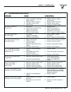
• Start the unit and apply full load according to the
following chart:
• Allow the unit to stabilize; then, turn the adjust-
ment screw slowly clockwise or counterclockwise
and watch the frequency.
• When the highest frequency is reached, turn the
adjustment screw counterclockwise 1/4 turn.
• The fuel system is now set.
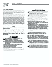
• For LP gas operations, the hose and blanking plug
must be reconfigured as shown in Figure 1.3, Page
7. The unit is set to provide maximum power
using LP gas.
Do not make any unnecessary adjustments.
Factory settings are correct for most applica-
tions. However, when making adjustments, be
careful to avoid overspeeding the engine.
Section 3 — Post-installation Start-up Adjustments
Guardian Air-cooled Generators
Unit 120 Volts 240 Volts
6 kW (Non-SA): 50 amps 25 amps
8 kW (Non-SA)
: 66.7 amps 33.3 amps
10 kW (Non-SA): 83.3 amps 41.6 amps
Sound Attn.: 66.7 amps 33.3 amps