


Generac
®
Power Systems, Inc. 7
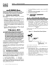
1.6 FUEL REQUIREMENTS
AND RECOMMENDATIONS
With LP gas, use only the vapor withdrawal
system. This type of system uses the vapors formed
above the liquid fuel in the storage tank.
The engine has been fitted with a fuel carburetion
system that meets the specifications of the 1997
California Air Resources Board for tamper-proof dual
fuel systems. The unit will run on natural gas or LP
gas, but it has been factory set to run on natural gas.
Should the primary fuel need to be changed to LP
gas, the fuel system needs to be reconfigured. See
Section 1.8 (Page 7) for instructions on reconfigura-
tion of the fuel system.
Recommended fuels should have a Btu content of at
least 1,000 Btus per cubic foot for natural gas; or at
least 2,520 Btus per cubic foot for LP gas. Ask your
fuel supplier for the Btu content of your fuel.
Fuel pressure for both natural gas and liquid
propane set ups should be 11 inches to 14 inches
of water column (0.6 psi) at all load ranges.
NOTE:
A seperate gas line and regulator may be needed
to assure proper gas pressure (11-14”) to the gen-
erator. Low gas pressure can cause hard starting
and could affect engine durability.
1.7 FUEL CONSUMPTION
*Natural gas is in cubic feet per hour.
**LP is in gallons per hour/cubic feet per hour.
Gaseous fuels such as natural gas and liquid
propane (LP) gas are highly explosive. Even the
slightest spark can ignite such fuels and cause
an explosion. No leakage of fuel is permitted.
Natural gas, which is lighter than air, tends to
collect in high areas. LP gas is heavier than air
and tends to settle in low areas.
1.8 RECONFIGURING THE
FUEL SYSTEM
1.8.1 7 KW
To reconfigure the fuel system from NG to LP,
follow these steps:
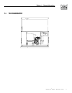
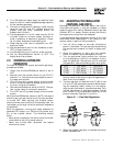
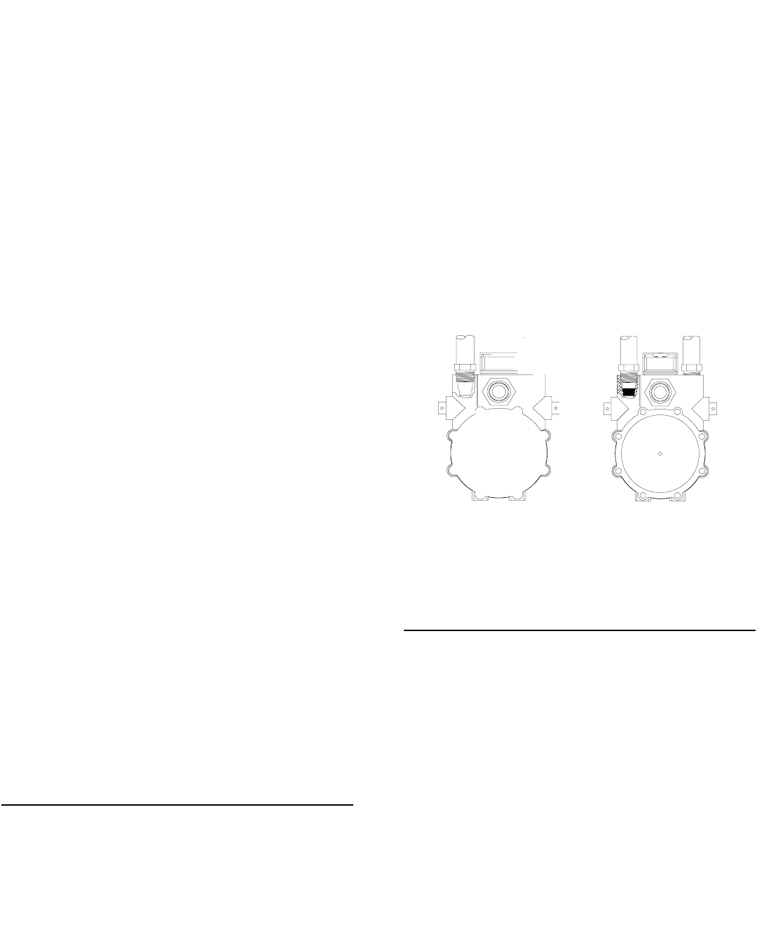
1. Turn the main gas supply off.
2. Remove the carburetor fuel hose(s) from the outlet
port(s) of the demand regulator (Figure 1.4).
3. Disconnect wire #0 and wire #14 from the gas
solenoid located on the top of the demand regu-
lator.
4. Remove the demand regulator by rotating coun-
terclockwise.
5. Remove the brass hose fitting(s) from the outlet
port of the demand regulator.
6. Remove the brass metering jet(s) (loosen coun-
terclockwise) from the housing port of the
demand regulator located on the side of the regu-
lator.
7. Install new LP metering jet(s) (tighten clockwise)
in the outlet port of the demand regulator.
8. Refit the brass hose fittings to the outlet port of
the demand regulator.
9. Reverse procedure steps 1-4 to reinstall demand
regulator.
10. Reverse the procedure to convert back to natural
gas.
Figure 1.4 – Demand Regulator
NOTE:
The natural gas adjustment screw is preset during
installation and should not need any further
adjustment.
1.8.2 V-TWIN
To reconfigure the fuel system from NG to LP,
follow these steps:
NOTE:
The primary regulator for the propane supply is
NOT INCLUDED with the generator. You must sup-
ply a fuel pressure of 11 to 14 inches of water col-
umn (0.6 psi) to the fuel inlet of the generator.
1. Locate the fuel demand regulator underneath the
control panel.
2. Identify both fuel adjustment screws.
NOTE:
One adjustment screw can be accessed from the
front of the unit and the second can be accessed
from the back of the unit.
◆