


20 Generac
®
Power Systems, Inc.
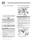
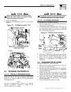
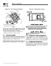
Figure 4.10 - Valve Clearance Adjustment
• Install new valve cover gasket.
• Re-attach the valve cover.
NOTE:
Start all four screws before tightening or you will
not be able to get all the screws in place. Make
sure the valve cover gasket is in place.
• Re-attach the spark plug wire to the spark plug.
• Repeat the process for the other cylinder.
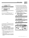
4.9 COOLING SYSTEM
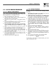
Air inlet and outlet openings in the generator compart-
ment must be open and unobstructed for continued
proper operation. This includes such obstructions as
high grass, weeds, brush, leaves and snow.
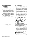
Without sufficient cooling and ventilating air flow, the
engine/generator quickly overheats, which causes it to
quickly shut down. (See Figure 4.9 for vent locations.)
Figure 4.9 – Cooling Vent Locations
The exhaust from this product gets extremely hot
and remains hot after shutdown. High grass,
weeds, brush, leaves, etc. must remain clear of
the exhaust. Such materials may ignite and burn
from the heat of the exhaust system.
The maximum ambient temperature for your
generator is 48.9° C (104° F).
4.10 ATTENTION AFTER SUBMERSION
If the generator has been submerged in water,
it MUST NOT be started and operated. Following any
submersion in water, have a Generac/Guardian
Authorized Dealer thoroughly clean and dry the generator.
4.11 CORROSION PROTECTION
Periodically wash and wax the enclosure using automo-
tive type products. Frequent washing is recommended
in salt water/coastal areas. Spray engine linkages with
a light oil such as WD-40.
!
Jam Nut
Pivot Ball
Stud
Rocker
Arm
Valve
Stem
Section 4 — Maintenance
Guardian Air-cooled 7 kW, 12 kW and 15 kW Generators