


Generac
®
Power Systems, Inc. 11
8. Turn ON electrical loads. Apply an electrical load
equal to the full rated wattage/amperage capacity
of the installed generator.
9. Connect an accurate AC frequency meter across
terminal lugs E1 and E2. Voltage should be
greater than 230 volts; frequency should be
greater than 58 Hertz.
10. Let the generator run at full rated load for 20-30
minutes. Listen for unusual noises, vibration or
other indications of abnormal operation. Check
for oil leaks, evidence of overheating, etc.
11. When testing under load is complete, turn OFF
electrical loads.
12. Set the generator's main circuit breakers to their
OFF (or open) positions.
13. Let the engine run at no-load for a few minutes.
14. Set the Auto/Off/Manual switch to OFF. The
engine should shut down.
2.5 CHECKING AUTOMATIC
OPERATION
To check the system for proper automatic operation,
proceed as follows:
1. Check that the Auto/Off/Manual switch is set to
OFF.
2. Manually set the transfer switch to the UTILITY
position, i.e., load terminals connected to the util-
ity power source side.
3. Turn ON the utility power supply to the transfer
switch, using the means provided (such as a util-
ity main line circuit breaker).
4. Set the Auto/Off/Manual switch to AUTO. The sys-
tem is now ready for automatic operation.
5. Turn OFF the utility power supply to the transfer
switch.
With the Auto/Off/Manual switch at AUTO, the engine
should crank and start when the utility source power
is turned OFF. After starting, the transfer switch
should connect load circuits to the standby side. Let
the system go through its entire automatic sequence
of operation.
With the generator running and loads powered by
generator AC output, turn ON the utility power sup-
ply to the transfer switch. The following should
occur:
• After about six seconds, the switch should transfer
loads back to the utility power source.
• About one minute after retransfer, the engine
should shut down.
2.6 ADJUSTING THE REGULATOR
(NATURAL GAS ONLY)
Although the generator has been factory set to pro-
vide maximum power, it may be necessary in some
areas to adjust this setting. Because natural gas has
different BTU or power content across the country
the engine may not perform as designed.
If you experience engine problems at high or full load
conditions follow these steps. It will require a fre-
quency meter to perform this procedure.
1. Turn off utility power to the main distribution
panel in the house. This can be done by switching
the service main breaker to the off or open posi-
tion.
2. Allow the generator to start and the transfer
switch to transfer load to emergency circuits.
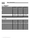
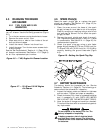
3. Turn on appliances, lights, pumps, etc., that are
on the emergency circuits in an attempt to fully
load the generator. Be cautious not to overload
the generator. Use the following chart as a guide:
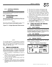
4. When full load has been achieved. Connect a fre-
quency meter to the output lugs of the generator’s
main line circuit breaker.
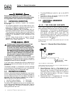
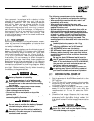
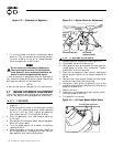
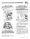
5. The fuel regulator is fitted with one (7 kW), or two
(12 and 15 kW) adjustment screws. While watch-
ing the frequency meter, slowly turn the adjust-
ment screw clockwise or counterclockwise. Only
limited adjustment is available between the set
pins. Under no circumstances should any of the
pins be removed (Figures 2.1 and 2.2).
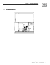
Figure 2.1 — Dual Fuel Regulators
6. When the highest frequency is reached maximum
power has been set.
410
Adjustment
Screw
(One Side
Only)
Set
Pins
V Twin
Set
Pins
Adjustment
Screw
(Both sides)
Section 2 — Post Installation Start-up and Adjustments
Guardian Air-cooled 7 kW, 12 kW and 15 kW Generators
Unit 120 Volts 240 Volts
7 kW 50.0 amps 25.0 amps
12 kW 83.3 amps 41.6 amps
15 kW 108.3 amps 54.1 amps