


10 Generac
®
Power Systems, Inc.
2.2 CHECK TRANSFER SWITCH
OPERATION
Refer to Section 3.5 (Page 14), of the owner’s manual
for manual operation procedures.
Do not attempt manual transfer switch opera-
tion until all power voltage supplies to the
transfer switch have been positively turned off.
Failure to turn off all power voltage supplies
will result in extremely hazardous and possibly
fatal electrical shock.
2.3 ELECTRICAL CHECKS
Complete electrical checks as follows:
1. Turn on the utility power supply to the transfer
switch using the means provided (such as a utili-
ty main line circuit breaker).
The transfer switch is now electrically “hot.”
Contact with “hot” parts will result in extreme-
ly hazardous and possibly fatal electrical shock.
Proceed with caution.
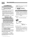
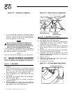
2. Use an accurate AC voltmeter to check utility
power source voltage across terminals N1 and
N2. Nominal line-to-line voltage should be 240
volts AC.
3. Check utility power source voltage across termi-
nals N1 and the transfer switch neutral lug; then
across terminal N2 and neutral. Nominal line-to-
neutral voltage should be 120 volts AC.
4. When certain that utility supply voltage is com-
patible with transfer switch and load circuit rat-
ings, turn OFF the utility power supply to the
transfer switch.
5. Set the generator's main circuit breaker to its
OFF (or open) position. Initial tests will be con-
ducted at no-load condition.
6. On the generator panel, set the Auto/Off/Manual
switch to MANUAL. The engine should crank and
start.
7. Let the engine warm up for about five minutes to
allow internal temperatures to stabilize. Then, set
the generator’s main circuit breaker to its ON (or
closed) position.
Proceed with caution! Generator power voltage
is now supplied to the transfer switch. Contact
with live transfer switch parts will result in
dangerous and possibly fatal electrical shock.
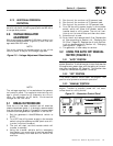
8. Connect an accurate AC voltmeter and an AC fre-
quency meter across transfer switch terminal
lugs E1 and E2. Voltage should be 242-252 volts;
frequency should read about 61-63 Hertz.
9. Connect the AC voltmeter test leads across termi-
nal lug E1 and neutral; then across E2 and neu-
tral. In both cases, voltage reading should be 121-
126 volts AC.
10. Set the generator’s main circuit breaker to its
OFF (or open) position. Let the engine run at no-
load for a few minutes to stabilize internal engine
generator temperatures.
11. Set the generator's Auto/Off/Manual switch to
OFF. The engine should shut down.
NOTE:
It is important that you do not proceed until you
are certain that generator AC voltage and frequen-
cy are correct and within the stated limits.
Generally, if both AC frequency and voltage are
high or low, the engine governor requires adjust-
ment. If frequency is correct, but voltage is high or
low, the generator’s voltage regulator requires
adjustment.
2.4 GENERATOR TESTS UNDER LOAD
To test the generator set with electrical loads applied,
proceed as follows:
1. Set generator’s main circuit breaker to its OFF
(or open) position.
2. Set the generator's Auto/Off/Manual switch
to OFF.
3. Turn OFF the utility power supply to the transfer
switch, using the means provided (such as a util-
ity main line circuit breaker).
Do not attempt manual transfer switch opera-
tion until all power voltage supplies to the
transfer switch have been positively turned off.
Failure to turn off all power voltage supplies
will result in extremely hazardous and possibly
fatal electrical shock.
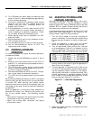
4. Manually set the transfer switch to the STANDBY
position, i.e., load terminals connected to the
generator's E1/E2 terminals. The transfer switch
operating lever should be down.
5. Set the generator's Auto/Off/Manual switch to
MANUAL. The engine should crank and start
immediately.
6. Let the engine stabilize and warm up for a few
minutes.
7. Set the generator’s main circuit breaker to its ON
(or closed) position. Loads are now powered by
the standby generator.
DANGER
DANGER
DANGER
Section 2 — Post Installation Start-up and Adjustments
Guardian Air-cooled 7 kW, 12 kW and 15 kW Generators