


Only qualified electricians or contractors should
attempt such installations, which must comply strictly
with applicable codes, standards and regulations.
1.1 UNPACKING/INSPECTION
After unpacking, carefully inspect the contents
for damage.
• This standby generator set has been factory sup-
plied with a weather protective enclosure that is
intended for outdoor installation only.
• This standby generator set is packaged with an
automatic transfer switch with built in load center.
The combination transfer switch and load center is
pre-wired with a 2 foot and 30 foot conduit. Circuit
breakers for emergency circuit connections are
included.
• This UL listed, 2-pole switch is rated at 100 AC
amperes at 250 volts maximum. This transfer
switch is for indoor use only.
If this generator is used to power electrical load
circuits normally powered by a utility power
source, you are required by code to install a trans-
fer switch. The transfer switch must effectively iso-
late the electrical system from the utility distribu-
tion system when the generator is operating (NEC
700, 701 & 702). Failure to isolate an electrical sys-
tem by such means will result in damage to the
generator and also may result in injury or death to
utility power workers due to backfeed of electrical
energy.
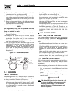
If any loss or damage is noted at time of delivery, have
the person(s) making the delivery note all damage on
the freight bill or affix his or her signature under the
consignor's memo of loss or damage.
If you note loss or damage after delivery, separate the
damaged materials and contact the carrier for claim
procedures.
“Concealed damage” is understood to mean damage
to the contents of a package that is not in evidence at
the time of delivery, but is discovered later.
1.2 PROTECTION SYSTEMS
Unlike an automobile engine, the generator may have to
run for long periods of time with no operator present to
monitor engine conditions. For that reason, the engine is
equipped with the following systems that protect it
against potentially damaging conditions:
1. Low Oil Pressure Sensor 3. Overcrank
2. High Temperature Sensor 4. Overspeed
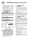
There are LED readouts on the control panel to noti-
fy you that one of these faults has occurred. There is
also a “System Set” LED that is lit when all of the con-
ditions describe in Section 1.3 are true.
1.3 SYSTEM SET LED
The “System Set” LED is lit when all of the following
conditions are true:
1. The Auto/Off/Manual switch is set to the AUTO
position.
2. The utility voltage being supplied to the unit is
being sensed by the PCB. If the utility sense volt-
age is not connected to the unit or if it is below
168 volts AC, then the system set light will flash
rapidly. This indicates that if the Auto/Off/Manual
switch is placed in the Auto position , the genera-
tor will start.
3. The “Not In Auto” dip switch is set to the OFF
position on the control board.
4. No alarms are present, for example, low oil pres-
sure, high temperature, etc.
DANGER
Section 1 — General Information
Guardian Air-cooled 7 kW, 12 kW and 15 kW Generators
4 Generac
®
Power Systems, Inc.