


12 Generac
®
Power Systems, Inc.
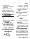
3. Turn on appliances, lights, pumps, etc., that are
on the emergency circuits in an attempt to fully
load the generator. Be cautious not to overload
the generator. Use the following chart as a guide:
4. When full load has been achieved. Connect a fre-
quency meter to the output lugs of the generator’s
main line circuit breaker.
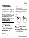
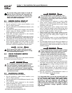
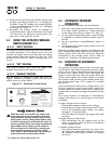
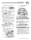
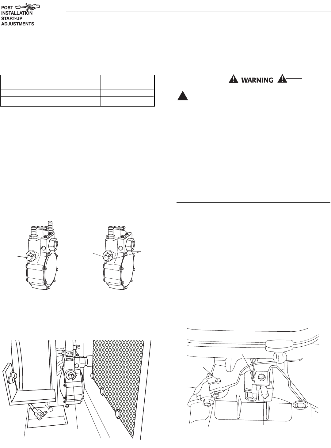
5. The fuel regulator is fitted with one (7 kW), or two
(12 & 15 kW) adjustment screws. While watching
the frequency meter, slowly turn the adjustment
screws clockwise or counterclockwise one at a
time until the highest frequency is read on the
meter. Only limited adjustment is available
between the set pins (7 kW only). Under no cir-
cumstances should any of the pins be removed
(Figures 2.1 and 2.2).
Figure 2.1 — Dual Fuel Regulators
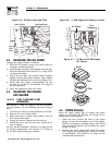
6. When the highest frequency is reached maximum
power has been set. From this point turn both
adjustment screws 1/4 turn counterclockwise.
The regulator is now set.
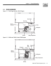
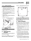
Figure 2.2 — Placement of Regulator
7. Turn utility power to the main distribution panel
back on. This can be done by switching the serv-
ice main breaker to the on or closed position.
Allow the generator to shut down.
Do not make any unnecessary adjustments.
Factory settings are correct for most applica-
tions. However, when making adjustments, be
careful to avoid overspeeding the engine.
If this procedure or equipment are not available to
you, locate the Generac Guardian Dealer nearest you
and they can perform the adjustments.
NOTE:
A service fee may be charged for this adjustment.
2.7 ENGINE GOVERNOR ADJUSTMENT
If both AC frequency and voltage are correspondingly
high or low, adjust the engine governor as follows:
2.7.1 7 KW UNITS
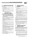
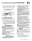
1. Loosen the governor clamp bolt (Figures 2.3 on
page 13).
2. Hold the governor lever at its wide open throttle
position, and rotate the governor shaft clockwise
as far as it will go. Then, tighten the governor
lever clamp bolt to 70 inch-pounds (8 N-m).
3. Start the generator; let it stabilize and warm up
at no-load.
4. Connect a frequency meter across the generators
AC output leads.
5. Turn the speed adjust nut to obtain a frequency
reading of 63 Hz.
6. When frequency is correct at no load, check the
AC voltage reading. If voltage is incorrect, the volt-
age regulator may require adjustment.
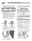
Figure 2.3 — Engine Governor Adjustment
Governor Clamp Bolt
Governor
Shaft
(Rotate
Clockwise)
Idle Spring
No Load Idle
Adjustment Screw
◆
!
Adjustment Screw
410
Adjustment
Screw
(One Side
Only)
Set
Pins
990
Adjustment
Screw
(Both sides)
Section 2 — Post Installation Start-up and Adjustments
Guardian Air-cooled 7 kW, 12 kW and 15 kW Generators
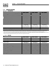
Unit 120 Volts 240 Volts
7 kW 50.0 amps 25.0 amps
12 kW 100.0 amps 50.0 amps
15 kW 108.3 amps 54.1 amps