


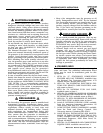
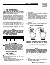
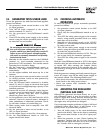
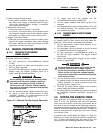
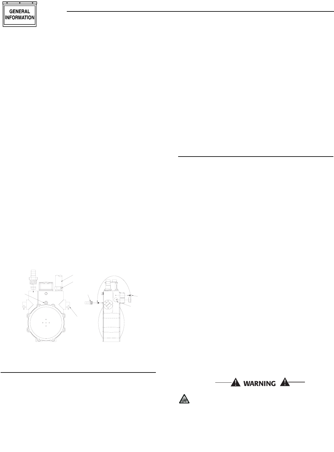
5. Remove the small brass hose fitting from the idle
circuit port of the regulator housing.
6. Remove the small jet (0D5698A) located in the
side of the regulator housing and install it into the
small threaded hole in the idle circuit port on the
regulator.
7. Refit the brass hose fitting to the idle circuit port
of the regulator. Use pipe thread sealant to reseal
the threads on the hose fitting.
8. Identify both adjustment screws.
NOTE:
One adjustment screw can be accessed from the
front of the unit and the second can be accessed
from the back of the unit.
9. Reverse procedure steps 1-4 to re-install the
demand regulator.
10. To adjust the system to run on LP fuel, simply
turn the adjuster screw that is accessed from
inside the front of the unit, 1/4 turn clockwise.
This will now set the system for maximum power
and best performance on LP fuel.
11. The fuel system will now allow the engine to run
on LP fuel. It may be necessary to make minor
adjustments to the preset screw settings to
achieve maximum power. If you experience prob-
lems with the unit producing maximum power,
follow the procedure in Section 2.6 (Adjusting the
Regulator).
Figure 1.4 - Demand Regulator
1.9 LOCATION
1.9.1 GENERATOR
Install the generator set, in its protective enclosure,
outdoors, where adequate cooling and ventilating air
is always available. Consider these factors:
• Install the unit where air inlet and outlet openings
will not become obstructed by leaves, grass, snow,
etc. If prevailing winds will cause blowing or drift-
ing, you may need to consider using a windbreak
to protect the unit.
• Install the generator on high ground where water
levels will not rise and endanger it.
• Allow sufficient room on all sides of the generator
for maintenance and servicing. A good rule is to
allow 5 feet of space on all sides.
• Where strong prevailing winds blow from one
direction, face the generator air inlet openings to
the prevailing winds.
• Install the generator as close as possible to the fuel
supply, to reduce the length of piping.
• Install the generator as close as possible to the
transfer switch. HOWEVER, REMEMBER THAT
LAWS OR CODES MAY REGULATE THE DIS-
TANCE.
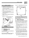
1.9.2 TRANSFER SWITCH
1.9.2.1 7 kW, 12 kW and 15 kW Units
The transfer switch shipped with this generator is
enclosed in a NEMA 1 enclosure. This type of enclo-
sure is intended for indoor use only. Follow these
rules:
• Install the transfer switch indoors on a firm, stur-
dy supporting structure.
• To prevent switch distortion, level the switch if nec-
essary. This can be done by placing washers
between the switch enclosure and mounting sur-
face.
• Never install the switch where water or any corro-
sive substance might drip onto the enclosure.
• Protect the switch at all times against excessive
moisture, dust, dirt, lint, construction grit and
corrosive vapors.
1.10 BATTERY INSTALLATION
Fill the battery with the proper electrolyte fluid if nec-
essary and have the battery fully charged before
installing it.
Before installing and connecting the battery, complete
the following steps:
1. Set the generator's Auto/Off/Manual switch to
OFF.
2. Turn off utility power supply to the transfer
switch.
3. Remove the 5A and 15A fuses from the generator
control panel.
If the Auto/Off/Manual switch is not set to its
OFF position, the generator can crank and start
as soon as the battery cables are connected. If
the utility power supply is not turned off,
sparking can occur at the battery posts and
cause an explosion.
◆
◆
PRESSURE
U
1
T
O
TAP
1/8 NPT
IDLE CIRCUIT
PORT
BRASS HOSE
FITTING
BRASS HOSE
FITTING
FUEL HOSE
ADJUSTER
SCREWS
REGULATOR
HOUSING PORT
SMALL
FUEL JET
Section 1 — General Information
Guardian Air-cooled 7 kW, 12 kW and 15 kW Generators
8 Generac
®
Power Systems, Inc.