


14 Generac
®
Power Systems, Inc.
Section 3 — Operation
Guardian Air-cooled 7 kW, 12 kW and 15 kW Generators
11. Drain the oil and remove the oil filter. Replace the
oil filter according to Section 4.4, “Changing the
Oil Filter” (Page 18). Replace the oil with synthet-
ic oil as recommended in Section 4.3, “Changing
the Engine Oil” (Page 17).
12. Reconnect the battery cables as outlined in
“General Hazards” (page 2) and insert the 5A and
15A fuses into the generator control panel. The
generator is now ready for service.
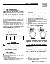
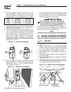
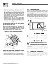
3.2 USING THE AUTO/OFF/MANUAL
SWITCH (FIGURE 3.1)
3.2.1 “AUTO” POSITION
Selecting this switch position activates fully automat-
ic system operation. It also allows you to start and
exercise the engine every seven days with the setting
of the exercise timer (see Section 3.6, Page 16). This
position also is used for remote starting, when it is
set up.
3.2.2 “OFF” POSITION
This switch position shuts down the engine. This
position also prevents automatic operation.
3.2.3 “MANUAL” POSITION
Set the switch to Manual to crank and start the
engine. Transfer to standby power will not occur
unless there is a utility failure.
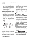
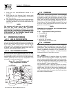
Figure 3.1 – Generator Control Panel
With the switch set to AUTO, the engine may
crank and start at any time without warning.
Such automatic starting normally occurs when
utility power source voltage drops below a pre-
set level or during the normal exercise cycle. To
prevent possible injury that might be caused by
such sudden starts, always set the switch to
OFF and remove the fuses before working on
or around the generator or transfer switch.
Then, place a “Do Not Operate” tag on the gen-
erator panel and on the transfer switch.
3.3 AUTOMATIC TRANSFER
OPERATION
To select automatic operation, do the following:
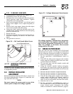
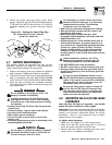
1. Make sure the transfer switch main contacts are
set to their “Utility” position, i.e., loads connected
to the utility power source (Figure 3.2, Page 15).
2. Be sure that normal utility power source voltage
is available to transfer switch terminal lugs N1
and N2.
3. Set the generator’s Auto/Off/Manual switch to
AUTO.
4. Set the generator’s main circuit breaker to its ON
(or closed) position.
With the preceding steps complete, the generator will
start automatically when utility source voltage drops
below a preset level. After the unit starts, loads are
transferred to the standby power source. Refer to
Section 3.4, “Sequence of Automatic Operation.”
3.4 SEQUENCE OF AUTOMATIC
OPERATION
The generator’s control panel houses a control logic
circuit board. This board constantly monitors utility
power source voltage. Should that voltage drop below
a preset level, circuit board action will signal the
engine to crank and start. After the engine starts, the
circuit board signals the transfer switch to activate
and connect load circuits to the standby power sup-
ply (load terminal lugs T1/T2 connect to terminal
lugs E1/E2).
Upon restoration of utility source voltage above a pre-
set level, generator circuit board action signals the
transfer switch to transfer loads back to that power
supply. After retransfer, the engine is signalled to shut
down.
The actual sequence of operation is controlled by
sensors and timers on a control logic circuit board,
as follows:
A.Utility Voltage Dropout Sensor
• This sensor monitors utility source voltage.
• If utility source voltage drops below about 70 per-
cent of the nominal supply voltage, the sensor
energizes a 15-second timer.
• Once the timer has expired, the engine will crank
and start.
B.Engine Warm-up Time Delay
• This mechanism lets the engine warm up for
about 10 seconds before the load is transferred
to the standby source.
C.Standby Voltage Sensor
• This sensor monitors generator AC output volt-
age. When the voltage has reached 50 percent of
the nominal rated voltage, transfer to standby
can occur.
!
HIGH TEMP.
OVER SPEED
LOW OIL
SYSTEM SET
OVER CRANK
MAN.
SET
OFFAUTO
15A
FUSE
EXERCISE
TIME
R
POWER SYSTEMS, INC.
Locate your nearest dealer at:
R
FUSE
5A
EXERCISER NOT SET
NO U T IL ITY SE N S E
4FLASHINGREDLEDS=
FLASHING GREEN LED=