


Generac
®
Power Systems, Inc. 13
Section 3 — Operation
Guardian Air-cooled 7 kW, 12 kW and 15 kW Generators
2.7.2 12 KW AND 15 KW UNITS
1. Loosen governor clamp bolt (See Figure 2.3).
2. Completely remove the idle spring.
3. With governor arm at wide open throttle position,
rotate governor shaft fully clockwise. Tighten
clamp bolt to 84 inch-pounds.
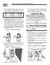
4. Start unit and apply full load. Use full load speed
adjust screw (Figure 2.4) to adjust frequency to
58 Hz.
5. Remove load, stop engine, loosen the idle adjust
screw and reconnect the idle spring.
6. Using your hand, push the governor arm to the
closed throttle position. Make sure the idle spring
does not stretch at all.
7. Restart the unit.
8. Slowly turn the idle adjust screw to adjust the no-
load idle frequency to 63-63.5 Hz (with door
open).
9. The governor is now set.
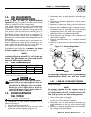
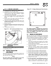
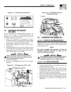
Figure 2.4 — Full Load Speed Adjust Screw
2.7.3 ADDITIONAL CORROSION
PROTECTION
Periodically spray all engine linkage parts and brack-
ets with corrosion inhibiting spray such as WD-40 or
a comparable product.
2.8 VOLTAGE REGULATOR
ADJUSTMENT
With the frequency between 62-63 Hertz, slowly turn
the slotted potentiometer (Figure 2.5) until line volt-
age reads 247-252 volts.
NOTE:
You must remove the access panel on top of the
control panel to adjust the voltage regulator.
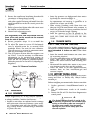
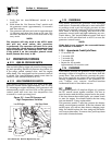
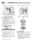
Figure 2.5 – Voltage Adjustment Potentiometer
NOTE:
The voltage regulator is housed above the genera-
tor's control panel. The regulator maintains a volt-
age in direct proportion to frequency at a 2-to-1
ratio. For example, at 62 Hertz, line-to-neutral
voltage will be 124 volts.
3.1 BREAK-IN PROCEDURE
Once the unit has been installed and all electrical
checks have been made, it is strongly recommended
that the following “Break-in Procedure” be completed
to ensure correct generator operation in the future.
1. Set the generator’s Auto/Off/Manual switch to
AUTO.
2. Turn OFF the utility power supply to the transfer
switch using the means provided (such as a utili-
ty main line circuit breaker).
3. The unit will start, and the transfer switch will
transfer to standby.
4. Using the transfer switch’s built-in emergency
load center, turn on circuits to load the generator
to approximately 25% rated load and run the unit
for one hour.
5. Run the unit for one hour at 50% rated load.
6. Run the unit for one hour at 75% rated load.
7. Run the unit for one hour at 100% rated load.
8. Turn ON the utility power supply to the transfer
switch, which will allow the transfer switch to
transfer back to utility power. The unit will con-
tinue to run for one minute and then shut down.
9. Allow the unit to cool.
10. Set the generator's Auto/Off/Manual switch to
OFF. Remove the 5A and 15A fuses from the gen-
erator control panel. Disconnect the battery
cables as outlined in “General Hazards” (page 2).
◆
Full Load Speed Adjust Screw
◆