


32 Generac
®
Power Systems, Inc.
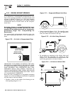
* For warm weather, use No. 2 cable up to 20 feet.
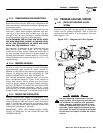
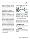
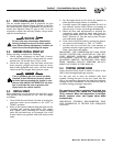
2.7.3 BATTERY CABLE CONNECTIONS
1. Connect the battery cable from the battery post or
terminal indicated by a POSITIVE, POS or (+) to
the large lug on the starter contactor as indicated
in Figure 2.23.
2. Connect the battery cable from the battery post
indicated by a NEGATIVE, NEG or (—) to the
frame ground connection.
Figure 2.23 — Connecting Battery Cables
NOTE:
If the generator compartment is grounded to the
vehicle chassis, it’s not necessary to connect a
NEGATIVE battery cable to the frame ground on
the generator base. Connect the negative cable to
the frame ground of the chassis.
3. Connect cables so the connections are clean and
tight.
2.7.4 BATTERY COMPARTMENT
Install the generator battery in its own, vented com-
partment. Place the battery compartment away from
any source of heat, sparks or flame.
Provide ventilation openings in the battery compart-
ment. The minimum size of openings should be 2
square inches at the top of the compartment. Mount
the battery on a strong, rigid supporting structure,
where leaks and spills of battery fluid will not cause
damage.
2.8 OPTIONAL ACCESSORIES
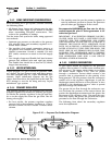
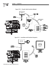
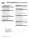
2.8.1 REMOTE PLUG-IN RECEPTACLE
A plug-in receptacle (Figure 2.24) is provided on the
generator set, near the DC power wires. Use this
receptacle to connect an optional remote-mounted
start/stop panel to the generator. Installation of such
a panel permits starting and stopping the generator
engine from any convenient location inside the vehi-
cle.
Figure 2.24 — Remote Panel Plug-In Receptacle
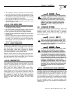
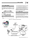
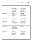
2.8.2 REMOTE START/STOP PANEL
A remote mounted Start/Stop panel (Figure 2.25) is
available that allows the user to start and stop the
generator engine conveniently from inside the vehicle.
The remote panel includes a Start/Stop switch,
hourmeter, generator run lamp and a wire harness.
Figure 2.25 — Optional Remote Panel
(Models 004057 and 004184)
The remote panels mount a rocker type start/stop
switch, a “Generator Run” advisory lamp and an
hourmeter. The hourmeter should be used in con-
junction with the maintenance operations found in
Part I of this manual.
• Model 004057 includes the remote panel and a 10
foot long, 4 wire harness.
• Model 004184 includes the remote panel and a 30
foot long, 4 wire harness.
◆
◆
◆
◆
Section 2 – Installation
IMPACT-36 plus II Recreational Vehicle Generator
CABLE LENGTH
in Feet (Meters) CABLE SIZE
0 to 10 (0 to 3) 2*
11 to 15 (3.4 to 4.5) 0
16 to 20 (4.9 to 6) 000
(13) To Panel
(16) To Starter
Starter
Contacter
Ground Wire
Positive Customer
Connection
(56) Controlled
12 Volts DC
Frame Ground