


24 Generac
®
Power Systems, Inc.
Section 2 – Installation
IMPACT-36 plus II Recreational Vehicle Generator
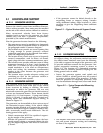
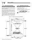
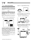
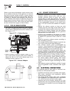
2.3.2 COOLING AIR INLET OPENINGS
Provide three air inlet openings, whether the genera-
tor is housed in a conventional compartment or not.
Two of the openings should be 10 square inches and
located as shown in Figure 2.10. The third opening
should provide for a minimum of 40 square inches
unrestricted and be located lower on the compart-
ment door.
NOTE:
Screening, louvers, or expanded metal that cover
air openings restrict air flow that must be com-
pensated for by making the actual air opening pro-
portionately larger. See “Compensating for
Restrictions.”
For conventional compartment mounted units, the
air inlet is generally provided in the compartment
door.
Figure 2.10 — Air Inlet in Compartment Door
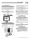
IMPORTANT: IF PLANNING TO INSTALL THE GEN-
ERATOR IN A COMPARTMENT, BE SURE TO LEAVE
AT LEAST ONE INCH (2” recommended) OF CLEAR-
ANCE BETWEEN THE GENERATOR AND COM-
PARTMENT WALLS AND CEILING. INCLUDE 26
GAUGE GALVANIZED STEEL LINING AND SOUND
INSULATION WHEN MEASURING FOR THIS 1 INCH
(2” recommended) CLEARANCE.
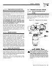
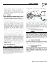
When the unit is installed on a suspended mounting
system, one of several different methods of supplying
air flow may be used as follows:
• Provide a door in the vehicle skirt having an air
inlet opening (Figure 2.11).
Figure 2.11 — Suspended Mount Inlet Door
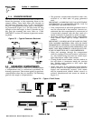
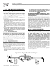
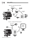
• Using ductwork (Figure 2.12). The installer must
be sure air is available to the top of the generator
since air inlets are located at the top.
Figure 2.12 — Air Inlet Using Ductwork
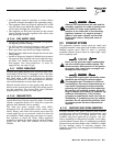
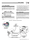
• By providing an opening in the vehicle skirt and
space above the generator for cooling air flow
(Figure 2.13). Recommended clearance above the
top of the generator is at least 2 inches.
Figure 2.13 — Air Inlet in Vehicle Skirt
◆
10 Square Inches
(Optional Openings)
40 Square Inches
(Minimum Opening)