


Generac
®
Power Systems, Inc. 29
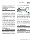
Section 2 – Installation
IMPACT-36 plus II Recreational Vehicle Generator
• Wiring must be of adequate size, with approved
insulative qualities, and properly supported.
• Conduit and wire openings into generator com-
partment (if used) must be vapor-sealed, to pre-
vent entry of flammable, explosive or poisonous
gases into the vehicle.
2.6.1 WIRING
• Wiring should be of stranded copper to reduce
chance that vibration may cause breakage.
• Wire gauge size of wires should be large enough to
handle at least 115% of the installed generator's
rated maximum current.
• If neutral conductors are used, they must be the
same size as other leg wires.
• Route power supply conductors from generator DC
output leads +DC (Red) and -DC (Blue), the return
(Black) and the ground (Green) wire through
approved flexible conduit, through the compart-
ment floor and to the terminal block located in the
DC junction box on the inverter. Refer to
ANSI/RVIA standard EGS-1-1993 for conduit
selection.
• If flexible metal conduit is used between the gener-
ator and the compartment junction box, the con-
duit end that terminates at the compartment junc-
tion box must be vapor-sealed. Flexible metal con-
duit is NOT vapor tight along its entire length.
• From the AC output junction box on the inverter,
route the three wires T1 (Black), T2 (White), and
the Green ground wire through approved flexible
conduit to either (a) double-pole, double-throw
transfer switch, or (b) approved isolation recepta-
cle. Connecting to a transfer switch or isolation
receptacle must prevent vehicle electrical circuits
from being connected to two different power sup-
plies at the same time (such as generator and
dockside power).
• Conductors must be rated 221°F (105°C) or must
be of a larger conductor size.
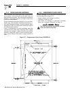
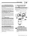
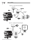
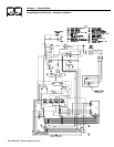
2.6.2 GENERATOR AC CONNECTION SYSTEM
The Impact plus AC generator output is provided by
the remote located inverter module. 120V AC is pro-
vided from the terminal block located inside one of
the J boxes on the inverter unit (Figure 2.19). The
unit is provided with a ground which is connected to
the generator and should be connected to the chassis
of the recreational vehicle.
Figure 2.19 — Inverter J Box for AC Output
Circuit breaker protection is provided on the genera-
tor and protects the unit against overload. Do not
apply loads which exceed the rated wattage, or
amperage capacity of the generator. Add the watts or
amperes of all lighting, appliance, tool and motor
loads that the generator will operate at one time. This
total should be less than the units rated
wattage/amperage capacity.
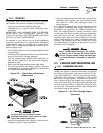
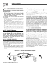
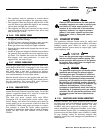
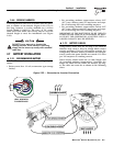
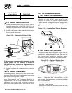
2.6.3 ISOLATING DIFFERENT POWER
SOURCES
Conductors from the junction box must terminate in
a double pole, double throw transfer switch (Figure
2.20). An alternate method for isolating different
power sources is by using an isolating receptacle
(Figure 2.21). Whichever method is used, be certain
that both power sources are NOT connected at the
same time.
2.6.4 POWER SUPPLY CORD
The power supply cord must comply with all applic-
able codes, standards and regulations. It must be
large enough to handle the full amperage to which it
will be subjected.
2.6.5 GROUND FAULT CIRCUIT
INTERRUPTERS
The National Electric Code (NFPA 70, 551-7)
requires installation of ground fault circuit inter-
rupters (GFCIs) on all external and some internal
electrical receptacles. Contact the dealer for recom-
mendations.
◆
◆
◆
◆
◆