


26 Generac
®
Power Systems, Inc.
Section 2 – Installation
IMPACT-36 plus II Recreational Vehicle Generator
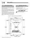
2.4.2 SOME IMPORTANT CONSIDERATIONS
When installing an LP gas system, consider seriously
the following items:
• All fittings, lines, hoses and clamps must be tight
and free of leaks. Apply a pipe sealant to threads
when assembling threaded connections. This
reduces the possibility of leakage.
Test the entire fuel system for leaks, using approved
test methods.
• Optimum gas pressure at the inlet to the gaseous
fuel solenoid valve and secondary regulator is 11
inches water column.
• The installer’s fuel supply connection point is at
the gaseous fuel solenoid valve. This is a 3/4 inch
(female) connection. Provide a suitable 3/4 inch
NPT (male) connector to attach to the fuel supply
line.
• Use a length of approved flexible fuel hose between
gaseous fuel solenoid valve and rigid gas piping.
The flexible line should be at least six (6) inches
longer than necessary.
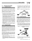
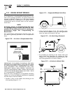
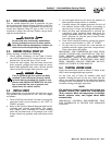
2.4.3 VAPOR WITHDRAWAL
Liquid propane (LP) gas is stored in pressure tanks
as a liquid. The gas systems used with these genera-
tors were designed only for “vapor withdrawal” type
systems. Vapor withdrawal systems use the gas
vapors that form above the liquid fuel in the tank, Do
NOT attempt to use the kit along with any “liquid
withdrawal” type system.
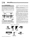
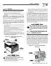
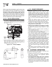
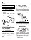
2.4.4 PRIMARY REGULATOR
Gas pressure delivered to the solenoid valve must be
properly regulated by means of a primary gas regula-
tor. Mount the primary regulator at the gas tank out-
let or in the supply line from the gas tank, The fol-
lowing rules apply:
• For best results, the primary regulator supplies
gaseous fuel to the secondary regulator at 11 inch-
es water column. Do NOT exceed 14 inches water
column.
• The installer must be sure the primary regulator is
rated at sufficient gas flow to operate the generator
plus all other gas appliances in the circuit.
NOTE:
Recommended MINIMUM gas flow rate for all air-
cooled Impact-34 plus II series generators is 67
cubic feet per hour.
IMPORTANT: IF AN EXISTING PRIMARY GAS REG-
ULATOR DOES NOT HAVE A SUFFICIENT FLOW
CAPACITY FOR THE GENERATOR AND OTHER
GAS APPLIANCES IN THE CIRCUIT, (a) INSTALL A
PRIMARY REGULATOR WITH ADEQUATE FLOW
RATE, OR (b) INSTALL A SEPARATE REGULATOR
RATED AT LEAST 67 CUBIC FEET PER HOUR. THE
INLET SIDE OF ANY PRIMARY REGULATOR THAT
SUPPLIES THE GENERATOR MUST CONNECT
DIRECTLY TO GAS TANK PRESSURE. DO NOT TEE
THE GENERATOR LINE INTO A GAS CIRCUIT
FEEDING OTHER APPLIANCES.
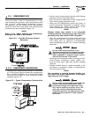
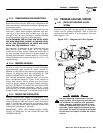
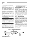
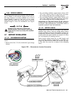
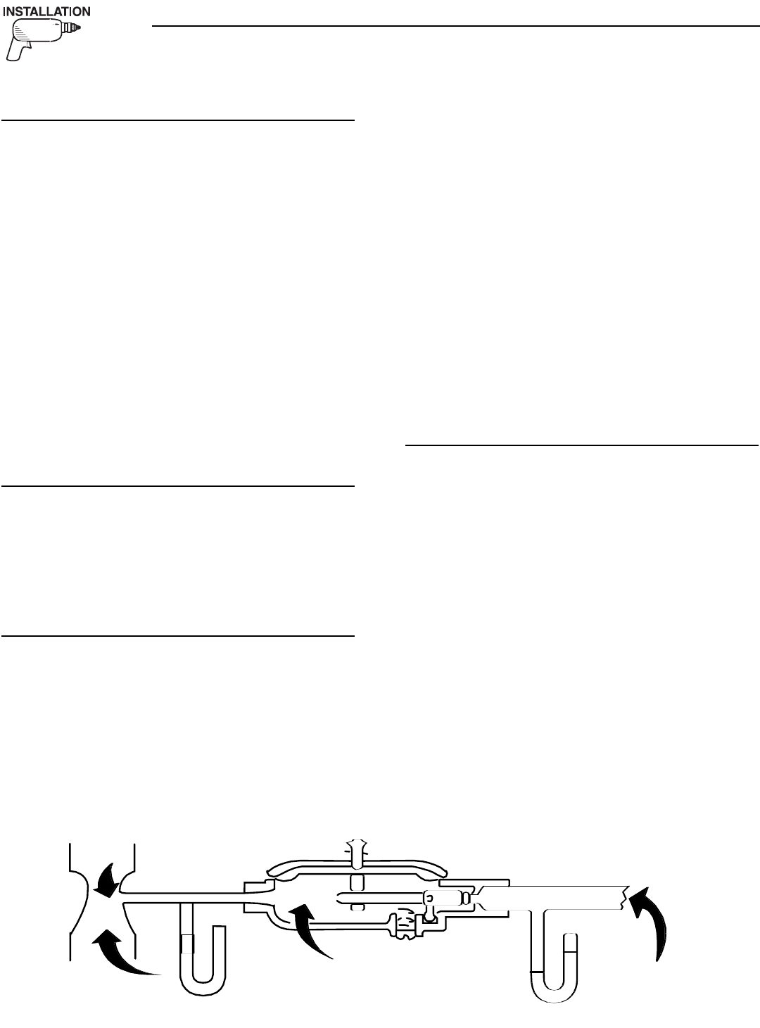
2.4.5 GASEOUS CARBURETION
LP gas vapors should be supplied to the generator
regulator inlet at about 11 inches water column (pos-
itive pressure). The engine piston draws air in during
the intake stroke (Figure 2.16). This air passes
through a carburetor venturi which creates a low
pressure that is proportional to the quantity of air
being pumped. The low pressure from the carburetor
venturi acts on the regulator diaphragm, to pull the
diaphragm toward the source of low pressure. A lever
attached to the diaphragm opens a valve to permit
gas flow through the carburetor.
The greater the air flow through the carburetor ven-
turi, the lower the pressure at the venturi throat, the
greater the diaphragm movement and the greater the
movement of the regulator valve. The more the regu-
lator valve opens, the greater the gas flow that is pro-
portional to air flow through the carburetor.
The following facts about the secondary regulator
must be emphasized:
◆
◆
◆
◆
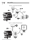
Figure 2.16 — Propane Gas Carburetion Diagram