


30 Generac
®
Power Systems, Inc.
2.6.2 WIRING
• Wiring should be of stranded copper to reduce the
chance that vibration may cause breakage.
• Wire gauge size should be large enough to handle
at least 115 percent of the installed generator's
rated maximum current.
• If neutral conductors are used, they must be the
same size as other leg wires.
• Route power supply conductors from generator AC
output leads T1 (red), T3 (black) and the green
ground wire through approved flexible conduit to
the electrical junction box on the compartment
wall.
If flexible metal conduit is used between the gener-
ator and the compartment junction box, the con-
duit end that terminates the compartment junction
box must be vapor-sealed. Flexible metal conduit
is NOT vapor tight along its entire length.
• From the junction box, route power supply wires
through approved conduit to either (a) double-
pole, double-throw transfer switch, or (b)
approved isolation receptacle. Connecting to a
transfer switch or isolation receptacle must pre-
vent vehicle electrical circuits from being connect-
ed to two different power supplies at the same time
(such as generator and dockside power).
• Conductors must be rated 221° F (105° C) or must
be of a larger conductor size.
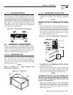
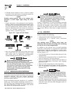
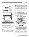
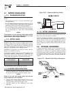
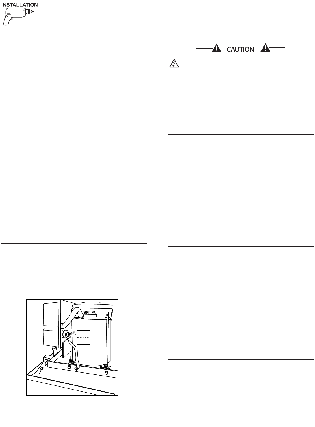
2.6.3 GENERATOR AC CONNECTIONS
Generator AC output leads T1 (red), and T3 (black)
come out of the generator as shown in Figure 2.17.
Lead T1 (red) is “hot”. There is also a green lead that
connects to ground in the junction box of the recre-
ational vehicle.
Figure 2.17 – Generator AC Output Leads
Do NOT connect electrical loads in excess of
any circuit breaker rating or you will develop
problems with circuit breaker tripping, which
causesalossofACoutput.Also,doNOT
exceed the generator's rated wattage capacity.
Add the watts or amperes of all lighting, appli-
ance, tool and motor loads the generator will
operate at one time. This total should be less
than the unit's rated wattage/amperage capaci-
ty.
2.6.4 CONDUIT
Route the connections between the generator and the
junction box through approved, flexible conduit. The
following general rules apply:
• Cut wiring to the required length and allow extra
wire for junction box connections.
• Carefully prepare conduit ends to prevent sharp
edges from cutting through wiring insulation.
• Route conduit so it does not interfere with genera-
tor movement.
• If you use metallic conduit, vapor seal the end of
the conduit where it enters the junction box. Do
this because flexible metallic conduit is not vapor
proof along its entire length.
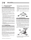
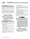
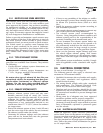
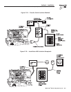
2.6.5 ISOLATING DIFFERENT POWER
SOURCES
Connections from the junction box must terminate in
a double-pole, double-throw transfer switch (Figure
2.18, Page 31). An alternate method for isolating dif-
ferent power sources is by using an isolating recepta-
cle (Figure 2.19, Page 31). Whichever method you
use, you must be certain that both power sources are
NOT connected at the same time.
2.6.6 POWER SUPPLY CORD
The power supply cord must comply with all applic-
able codes, standards and regulations. It must be
large enough to handle the full amperage to which it
will be subjected.
2.6.7 GROUND FAULT CIRCUIT INTER-
RUPTERS
The National Electrical Code (NFPA 70, 551-7)
requires that you install ground fault circuit inter-
rupters (GFCIs) on all external and some internal
electrical receptacles. Contact your manufacturer or
dealer for recommendations.
◆
◆
◆
◆
T3
T2
T1
Green
(Ground)
◆
◆
Section 2 – Installation
PRIMEPACT 50 and 70 (50Hz) Recreational Vehicle Generators