


22 Generac
®
Power Systems, Inc.
2.1 LOCATION AND SUPPORT
2.1.1 GENERATOR LOCATION
The most desirable location for the generator set is
between the vehicle's main frame members. However,
this is seldom possible. Most units must be installed
on the side of the vehicle and are difficult to reinforce.
Many recreational vehicles have been factory
equipped with an area for the generator set. Some
vehicles may even have a generator compartment
provided by the vehicle manufacturer.
Plan the generator location based on the following:
• The generator set must be installed on a frame-
work that is part of the recreational vehicle, as out-
lined in Section 2.1.2.
• The location must provide an access opening that
is large enough to permit generator removal
(unless the generator is to be removed from under-
neath the supporting framework).
• The location must provide easy access to frequent-
ly serviced components, such as filters, oil drains,
spark plugs and other common maintenance
parts.
• The location must provide sufficient room to allow
minimum clearances as outlined in Section 2.2. If
sound insulation is to be used on the compartment
walls and ceiling, the minimum recommended
applies to the space between the generator and
such insulation.
• The location must provide adequate cooling and
ventilating airflow for the generator without a great
deal of work and expense.
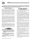
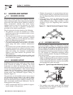
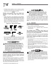
2.1.2 GENERATOR SUPPORT
The generator must be securely attached to a metal
framework that has been made part of the vehicle
frame structure by bolting or welding. The metal
framework on which the generator will rest and
which will restrain the generator set should consist of
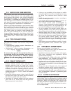
at least two horizontal beams. These beams should
consist of (a) 1-1/2-inch square, 11-gauge steel tubing
OR (b) 1-1/2-inch, 11-gauge angle iron. A typical sup-
porting frame with horizontal support tubing, is
shown in Figure 2.1.
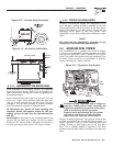
The generator can be installed so that it sits on top of
the horizontal support tubing if the vehicle design
permits. Another method is to suspend the generator
below the horizontal support tubing by means of suit-
able, structurally sound metal framework. The fol-
lowing general rules apply:
• Vehicle construction MUST be capable of support-
ing the weight of the generator.
• Whether the generator is mounted above the hori-
zontal support tubing or suspended below the tub-
ing, the supporting frame used must be structural-
ly sound.
• If the generator cannot be bolted directly to the
supporting frame or support tubing, consider
using additional tubing, angle brackets or other
supports to give the supporting frame sufficient
strength.
Figure 2.1 – Typical Horizontal Support Frame
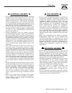
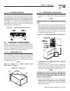
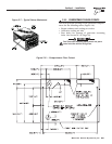
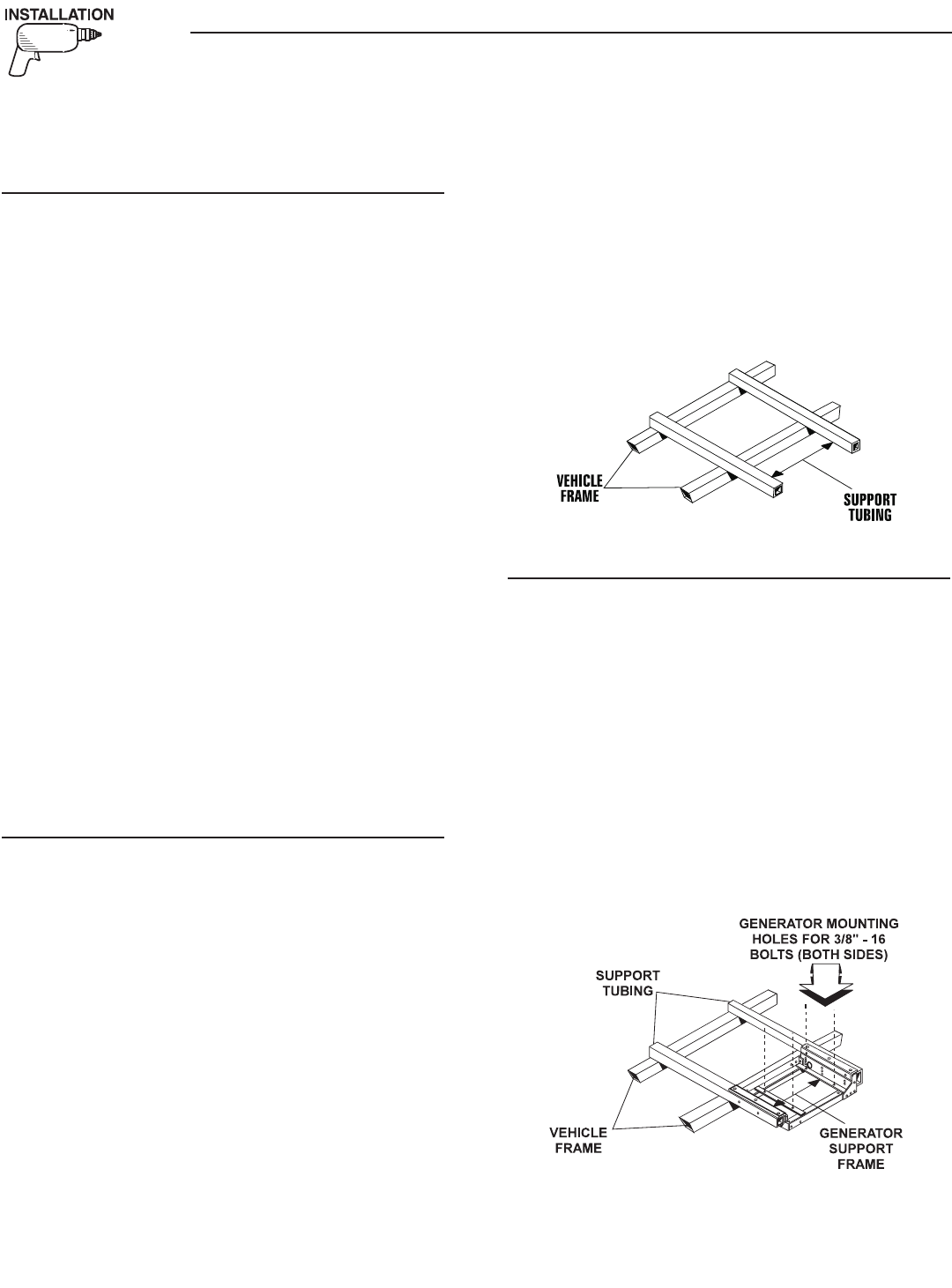
2.1.3 SUSPENDED MOUNTING
If you are going to suspend the generator below the
horizontal support tubing, the suspension method
you use with the vehicle frame members must (a) be
able to support the weight of the generator AND (b)
provide sufficient restraint for the generator. One typ-
ical suspended mounting system is shown in Figure
2.2. The location of a suspended mounting system
must be carefully planned, keeping the following gen-
eral rules in mind:
• Protect the generator against road splash and debris.
Baffles or splash guards may be required to protect
certain areas of the generator. To make sure the gen-
erator is adequately protected, road test the installa-
tion through mud, water and slush.
Figure 2.2 – Typical Suspended Mounting System
• The installer must make certain that the selected
location will permit adequate cooling and ventilat-
ing airflow to be supplied.
◆
◆
◆
Section 2 – Installation
PRIMEPACT 50 and 70 (50Hz) Recreational Vehicle Generators