


Generac
®
Power Systems, Inc. 9
Section 2 – Operation
PRIMEPACT 50 and 70 (50Hz) Recreational Vehicle Generators
2.6 STOPPING THE GENERATOR
1. Turn OFF all electrical loads using the means
provided (such as a main circuit breaker or
transfer switch).
2. Let generator run at no-load for a few minutes, to
stabilize internal engine generator temperatures.
3. Place the Start/Stop switch in its STOP position.
2.7 APPLYING LOADS TO GENERATOR
When applying electrical loads to the generator,
observe these guidelines:
• Before applying electrical loads, let the generator
stabilize and warm up for a minute or two.
• DO NOT overload the generator.
2.7.1 LETTING THE ENGINE STABILIZE
The generator supplies correct rated voltage only at
the proper governed speed. Some electrical appli-
ances may be extremely sensitive to voltage. Incorrect
voltages can damage such appliances.
If electrical loads are applied at reduced operating
speeds, such loads imposed on the engine when suffi-
cient power is not available may shorten engine life.
Never turn ON electrical loads until after the generator
engine has started and stabilized at no-load.
2.7.2 DO NOT OVERLOAD THE GENERATOR
You can read the rated wattage/amperage capacity of
your generator on the generator data decal (see
Section 1.1 on Page 4).
Applying electrical loads in excess of the unit’s rated
capacity will cause the engine/generator to automati-
cally shut down.
To avoid overloading, add up the wattage of all con-
nected electrical lighting, appliance, tool and motor
loads. This total should not be greater than the gen-
erator’s rated wattage capacity.
• Most lighting, appliance, tool and motor loads indi-
cate their required watts on their nameplate or
data plate. For light bulbs, simply note the wattage
rating of the bulb.
• If a load does not show its rated wattage, multiply
that load’s rated VOLTS times AMPS to obtain
WATTS.
• Induction type motors (such as those that run the
vehicle’s furnace fan, refrigerator, air conditioner,
etc.) need about 2-1/2 times more watts of power
for starting than for running (for a few seconds
during motor starting). Be sure to allow for this
when connecting electrical loads to the generator.
First, figure the watts needed to start electric
motors in the system. To that figure, add the run-
ning wattages of other items that will be operated
by the generator.
• Do not apply heavy electrical loads for the first two
or three hours of operation.
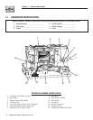
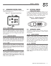
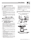
2.8 PROTECTION SYSTEMS
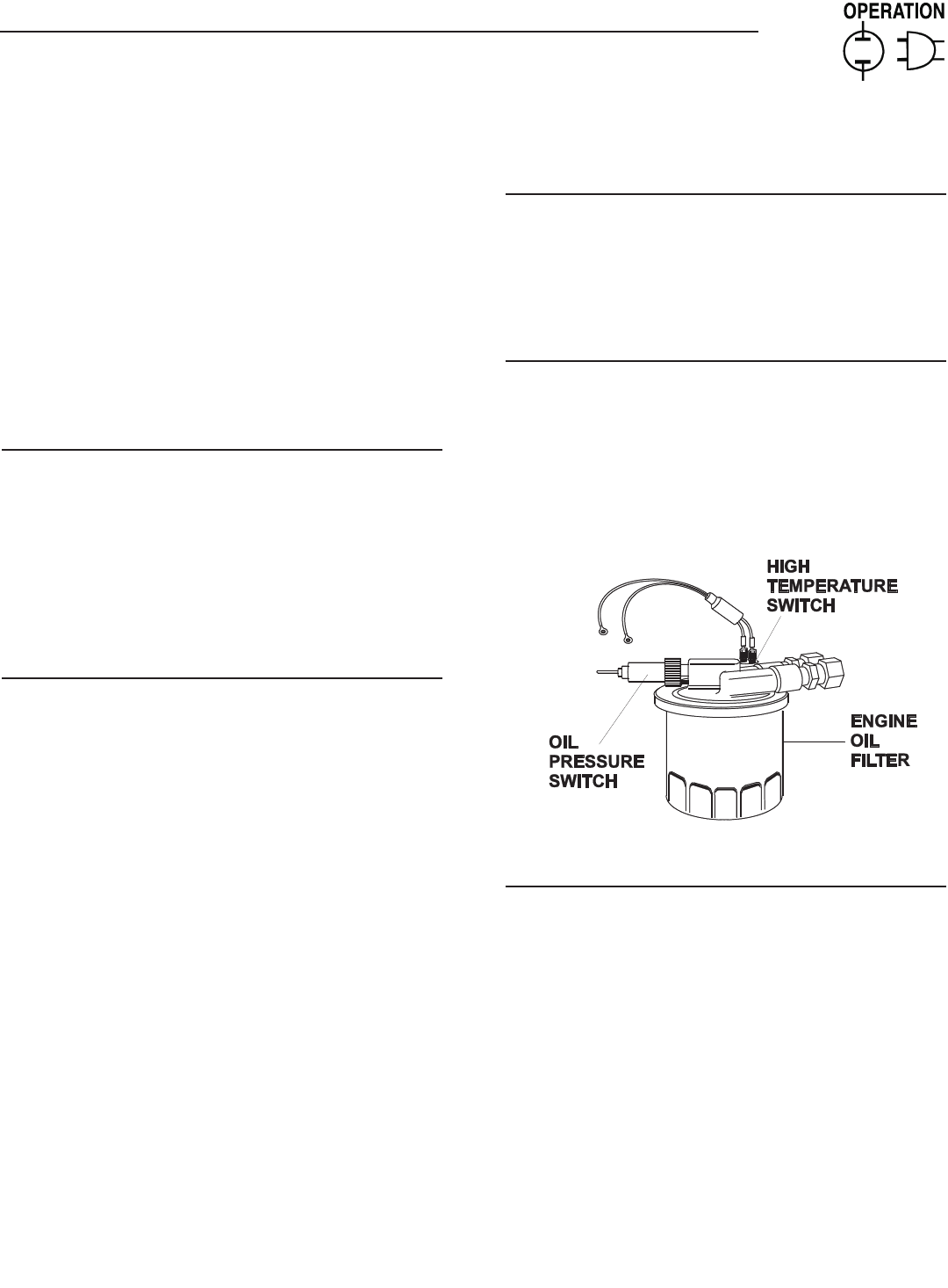
2.8.1 LOW OIL PRESSURE SWITCH
This switch (Figure 2.3) has normally open (N.O.) con-
tacts that are held open by engine oil pressure during
cranking and operating. Should oil pressure drop
below a preset level, switch contacts close, and the
engine automatically shuts down. The unit should not
be restarted until oil is added.
2.8.2 HIGH TEMPERATURE SWITCH
This switch (Figure 2.3), which has normally open
(N.O.) contacts, is mounted near the oil filter. The
contacts close if the temperature should exceed
approximately 284º F (140º C), initiating an engine
shutdown.
Figure 2.3 – Low Oil Pressure and
High Temperature Switches
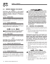
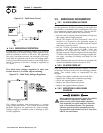
2.8.3 FIELD BOOST
The Controller Circuit Board houses a field boost
diode and resistor. These two components are part of
a “field boost” circuit (Figure 2.4). During engine
cranking only, a positive DC (battery) voltage is deliv-
ered through the diode, resistor, brushes and slip
rings, and the generator rotor. Application of this
voltage to the rotor “flashes the field” whenever it is
started. Flashing of the field each time the generator
starts makes sure that a sufficiently strong magnetic
field is available to produce “pickup” voltage in the
stator windings.
◆
◆
◆
◆
◆