


4
1.1 GENERATOR
This equipment is a liquid-cooled, engine-driven gen-
erator set. The generator is designed to supply elec-
trical power that operates critical electrical loads
during utility power failure. The unit has been facto-
ry-installed in a weather resistant, all metal enclosure
and is intended for outdoor installation only. Use this
generator as a source of electrical power for the oper-
ation of 120 and/or 240VAC, single-phase loads.
These models are available. They are rated as follows:
Model 005031-0: Provides 25,000 watts (25 kW) of single-
phase power.
Model 005028-0: Provides 20,000 watts (20 kW) of single-
phase power.
Model 005030-0: Provides 15,000 watts (15 kW) of single-
phase power.
If this generator is used to power electrical load
circuits normally powered by a utility power
source, it is required by code to install a trans-
fer switch. The transfer switch must effectively
isolate the electric system from the utility distri-
bution system when the generator is operating
(NEC 701). Failure to isolate an electrical system
by such means results in damage to the genera-
tor and may also result in injury or even death
to utility power workers due to backfeed of
electrical energy.
1.2 TRANSFER SWITCH
This generator system is intended to be used with a
matched automatic transfer switch. It may be supplied
in either a NEMA 1 enclosure or a NEMA 3R enclo-
sure. The NEMA 1 enclosure is intended for indoor
use only. The NEMA 3R enclosure is weather proof and
can be used indoors or outdoors. Follow these rules:
• Install the transfer switch on a firm, sturdy sup-
porting structure.
• To prevent switch distortion, level the switch if nec-
essary. This can be done by placing washers
between the switch enclosure and the mounting
surface.
• Never install the switch where water or any corro-
sive substance might drip onto the enclosure.
• Protect the switch at all times against excessive
moisture, dust, dirt, lint, construction grit and cor-
rosive vapors.
If a transfer switch is not included, one may be pur-
chased separately from an Authorized Dealer.
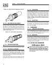
1.3 AUTOMATIC TRANSFER SWITCH
(ATS MODE)
When this generator, along with an HS Type automat-
ic transfer switch has been installed and connected,
a circuit board in the generator control panel con-
stantly monitors the utility voltage and controls the
operation of the transfer switch.
In ATS Mode utility voltage sensing, weekly exercis-
ing, and load transferring is under the control of the
generator.
Should the utility voltage drop below a preset value,
and remain at this low voltage for a preset amount of
time, the generator cranks and starts. After the gen-
erator starts, the transfer switch transfers the load
circuits to the generator so the generator can power
them. When the utility source voltage has been
restored, the transfer switch re-transfers the load cir-
cuits back to the utility source voltage and the gener-
ator shuts down.
1.4 ENGINEERED TRANSFER SWITCH
(2-WIRE START GTS MODE)
When required, the pre-packaged standby generator
can be installed with an engineered W-type transfer
switch which controls utility voltage sensing, weekly
exercising and load transferring.
UTILITY voltage sensing, weekly exercising and load
transferring is then under the control of the
Engineered W-type transfer switch (GTS Mode).
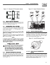
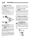
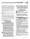
1.5 GENERATOR AC CONNECTION
SYSTEMS
The generator was shipped from the factory with its
stator AC output leads connected in a single-phase,
3-wire generator AC connection system (Figure 1.1).
The stator assembly in this system consists of a pair
of stationary windings, with two leads brought out of
each winding. Each single winding can supply 120
VAC, 60 Hertz. When the two windings are connected
in series, a 240 VAC, 60 Hertz AC output results.
Typically the two “hot” leads in the circuit are Wires
No. 11 and 44. The “Neutral” leads are the junction
of Wires 22 and 33.
!
Section 1 - General Information
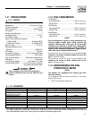
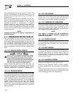
Liquid-cooled 15, 20 and 25 kW Generators
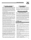
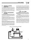
Model Rating Phase Actual Current C/B Rating* % over rating Circuit Breaker
005031-0 25,000 W 1 104.2 A 125 A 120% 125A BQ2
005028-0 20,000 W 1 83.3 A 100 A 120% 100A BQ2
005030-0 15,000 W 1 62.5 70 A 112% 70A BQ2
* Amp Rating of C/B structured under model.
Figure 1.2 - Main Circuit Breaker