


15
Section 3 - Operation
Liquid-cooled 15, 20 and 25 kW Generators
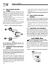
3.1 CONTROL CONSOLE
COMPONENTS
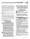
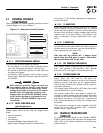
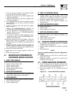
The components of a home standby generator control
console (Figure 3.1) are as follows:
Figure 3.1 - Generator Control Console
3.1.1 AUTO/OFF/MANUAL SWITCH
Use this three-position switch as follows:
• Set the switch to AUTO for fully automatic opera-
tion. See “Automatic Operation” (Section 3.6).
• Set switch to MANUAL position to crank and start
the generator engine.
• Set switch to OFF position to shut down an oper-
ating engine. With OFF selected, operation will not
be possible.
With switch set to AUTO, engine can crank and
start suddenly without warning. Such automat-
ic start up normally occurs when utility source
voltage drops below a pre-set level. To prevent
possible injury that might be caused by such
sudden starts, set AUTO/OFF/ MANUAL switch
to OFF before working on or around the unit.
Then, place a “DO NOT OPERATE” tag on con-
trol console.
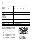
3.1.2 FAULT INDICATOR LEDS
(SEE CHART ON PAGE 16)
These red LEDs turn ON when one or more of the fol-
lowing engine faults occurs and the engine shuts
down.
• Low Oil Pressure
• Overcrank
• Low Battery
• Overspeed/Engine Speed Signal Fault
• High Coolant Temperature/Low Coolant Level
See Section 1.7 for further explanation of engine pro-
tection functions.
3.1.3 15 AMP FUSE
This fuse protects the control console’s DC control
circuit against electrical overload and is located
inside the control panel. If the fuse has melted open
because of an overload, engine cranking and startup
cannot occur. If the fuse needs to be replaced, use
only an identical 15-amp replacement fuse (type
ATO).
3.1.4 5 AMP FUSE
This fuse protects the battery charger against electri-
cal overload and is located inside the control panel. If
the fuse needs to be replaced, use only an identical 5-
amp replacement fuse (type ATO).
NOTE:
This fuse will not remove the + battery input
power from the PCB when it opens. This means
the exercise timer will not be reset.
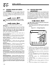
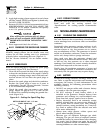
3.1.5 SET EXERCISE TIME SWITCH
This switch allows programming the generator to
start and exercise automatically. “See Weekly
Exercise Cycle” (see Figure 3.3 and Section 3.6).
3.1.6 SYSTEM READY LED
The System Ready LED (green) has two main pur-
poses. First, the LED will be ON when the
AUTO/OFF/MANUAL switch is in the AUTO position,
utility is present, and there are no system alarms.
This ON state indicates the system is fully ready for
automatic operation.
The system ready LED will be OFF when the switch
is in the MANUAL or OFF positions.
The system ready LED is also used to indicate the
presence of utility sensing at the PCB when the switch
is either in the AUTO or MANUAL modes. The LED
will flash at the rate of 1/2 second on, 1/2 second off
if the utility sensing level is below the transfer back
threshold.
This secondary function is only available with DIP
switch two in the OFF position (ATS - automatic
transfer switch application).
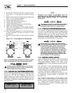
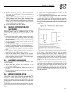
3.2 MANUAL TRANSFER AND
START-UP
To transfer electrical loads to the Standby (EMER-
GENCY) power source side and start the engine man-
ually, refer to the Owner’s Manual of the particular
transfer switch.
!
DANGER
C
A
U
TI
ON
RI
S
K
O
F ELE
C
TRI
C
AL
S
H
OC
K. D
O
N
O
T REM
O
VE
CO
VER. N
O
US
ER
S
ERVI
C
EABLE
PARTS INSIDE. REFER SERVICING TO
Q
UALIFIED SERVICE PERSONNEL
.
C
A
U
TI
ON
F
O
R
S
TAND-BY
S
ERVI
C
E
CO
NNE
C
T
OU
TP
U
T
O
F
G
ENERAT
O
R T
O
SU
ITABLY RATED
TRANSFER SWITCH IN ACCORDANCE WITH CANADIAN ELECTRICAL CODE
,
PART I
.
TENTION: POUR L'ALIMENTATION DE RESERVE, CONNECTER LA SORTIE DE
ATRICE A UN COMMUTATEUR DE CALIBRE APPROPRIE, CONFORMENENT AU
CANADIEN DE L'ECTRICITE
,
PREMIERE PARTIE
.
WARNIN
G
C
AN A
U
T
O
MATI
C
ALLY
S
TART AT ANYTIME WITH
OU
T N
O
TI
C
E
.
Y
REM
O
VE F
US
E
O
N
CO
NTR
O
L PANEL AND NE
G
ATIVE BATT
E
S
ERVI
C
IN
G.
WARNIN
G
THI
S
EMER
G
EN
C
Y P
O
WER
S
Y
S
TEM I
S
DE
S
I
G
NED EX
C
L
US
IVELY F
O
R
OU
TD
OO
R IN
S
TALLATI
O
N
O
NLY
!
0
E71
93
US
E
O
F
S
YNTHETI
C
O
IL I
S
RE
CO
MMENDE
D
ON
0
F2
6
2
9
THEN THE UNIT WILL START
,
RUN THROUGH THE EXERCISE CYCLE AND SHUTDOWN
.
MAN
U
A
L
S
E
T
EXER
C
I
SE
TIME
T
O
S
ET EXER
C
I
S
ER TIM
E
2
)
HOLD "SET EXERCISE TIME" SWITCH IN "ON" POSITION FOR THREE SECOND
S
AND RELEASE.
(
SEE OWNER'S MANUAL FOR COMPLETE DETAILS
)
THE EXER
C
I
S
ER I
S
N
O
W
S
ET. ALL FIVE RED LED'
S
WILL FLA
S
H F
O
R 1
0
S
E
CO
ND
S
1
)
PLACE AUTO/OFF/MANUAL SWITCH TO AUTO POSITION
.
O
VER
S
PEE
D
O
VER
C
RAN
K
L
O
W BATTER
Y
S
Y
S
TEM READ
Y
A
U
T
O
O
F
F
FLA
S
HIN
G
G
REEN LED = N
O
U
TILITY
S
EN
SE
5
FLA
S
HIN
G
RED LED'
S
= EXER
C
I
S
ER N
O
T
S
E
T
LED INDI
C
AT
O
R
S:
RED LED'
S
= INDIVID
U
AL FA
U
L
T
(
IN AUTO MODE ONLY
)
O
F
F
HI
COO
L. TEMP
.
L
O
W
COO
L. LEVE
L
L
O
W
O
IL PRE
SS.
(
SEE OWNER'S MANUAL FOR COMPLETE LED DETAILS
)
SOLID GREEN LED = SYSTEM READY
,
UTILITY POWER O
N