


10
2.4 BASIC STANDBY ELECTRIC
SYSTEM
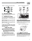
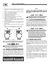
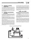
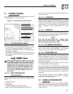
Figure 2.1 shows a schematic diagram of a basic
standby electric system. Both the UTILITY power
supply and the STANDBY GENERATOR output are
connected to an approved transfer switch. The trans-
fer switch is required by electrical code and serves
the following functions:
• Permits the LOAD circuits to be connected to only
one power supply at a time.
• Prevents electrical backfeed between the generator
and the UTILITY power circuits.
Notice that both the STANDBY and the UTILITY
power supplies to the transfer switch are protected
against overload by a main line circuit breaker.
Figure 2.1 – Basic Standby Electric System
NOTE:
The manufacturer recommends the use of a
Generac Power Systems transfer switch in con-
junction with this generator.
2.5 EMERGENCY CIRCUIT ISOLATION
METHOD
This prevents overloading the generator by keeping
electrical loads below the wattage/amperage capacity
of the generator. If the generator is powering only crit-
ical loads, within its wattage/amperage capacity, dur-
ing utility power outages, consider using the emer-
gency circuit isolation method.
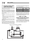
Critical electrical loads are grouped together and
wired into a separate “Emergency Distribution
Panel.” The generator only supplies electrical circuits
connected to the emergency distribution panel during
utility power outages. Load circuits powered by that
panel must be within the wattage/amperage capacity
of the generator set. The transfer switch must meet
the following requirements:
• It must have an ampere rating equal to the total
amperage rating of the emergency distribution
panel circuit.
• It must be installed between the building’s main
distribution panel and the emergency distribution
panel.
2.6 TOTAL CIRCUIT ISOLATION
METHOD
When a generator capable of powering all electrical
loads in the circuit is to be installed, the “Total
Circuit Isolation Method” may be used. The following
apply to the transfer switch in this type of system.
• Ampere rating of the transfer switch must equal
the ampere rating of the normal incoming utility
service.
• The transfer switch is installed between the utility
service entrance and the building distribution
panel.
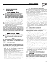
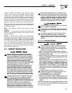
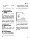
2.7 GROUNDING THE GENERATOR
A GROUNDING LUG (Figure 2.2) is provided on the
generator mounting base for the purpose of ground-
ing the frame and the external electrically conductive
parts of the equipment to an approved earth ground
and/or grounding rods where required by the
National Electrical Code. Consult a qualified electri-
cian for grounding requirements in the area.
Grounding procedures must meet local regulations.
Do not connect the ground wire to any pipe
that carries a flammable or explosive substance
– FIRE or an EXPLOSION may result.
Proper grounding helps protect personnel against
electrical shock in the event of a ground fault condi-
tion in the generator or in connected electrical
devices. In addition, grounding helps dissipate static
electricity that often builds up in ungrounded
devices.
Figure 2.2 – Generator Grounding Lug (typical)
DANGER
Section 2 — Installation
Liquid-cooled 15, 20 and 25 kW Generators