


12
2.10 ENGINEERED TRANSFER SWITCH
(2-WIRE START GTS MODE)
When required, the pre-packaged standby generator
can be installed with an engineered W Type transfer
switch which controls utility voltage sensing, weekly
exercising and load transferring.
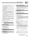
When Position 2 of the eight-position DIP switch,
which is located on the generator circuit board (See
Figure 3.2), is in the ON position then utility voltage
sensing, weekly exercising and load transferring is
under the control of the Engineered W Type transfer
switch (GTS Mode).
Generator DIP Switch Position 2 ON = 2-Wire Start
GTS Mode
• The generator control board will NOT monitor the
utility.
• The generator control board will NOT perform a
weekly exercise. (The five red LEDs will flash one
at a time in GTS mode.)
• The generator control board will NOT activate the
transfer output.
The generator control board WILL monitor all engine
conditions and shut down on all the faults listed in
this document.
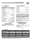
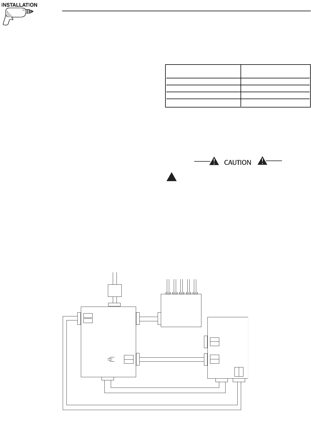
For the W Type transfer switch to control utility volt-
age sensing, weekly exercising and load transferring,
suitable wiring must also be connected from the
transfer switch 178 and 183, 2-Wire Start terminals
to the corresponding generator 178 and 183 2-Wire
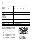
Start terminals. Recommended wire gauge sizes for
the 2-Wire Start wiring depend on the length of the
wire (see wiring length chart).
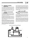
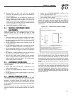
Route the 2-Wire Start control wires through suitable,
approved conduit which is separate from the AC
power leads. Connection of wire 178 to wire 183 by
relay contact closure action (volt free switch contacts)
in the transfer switch must result in generator engine
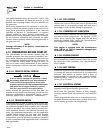
cranking and startup (See Figure 2.4).
Do NOT connect battery voltage, utility voltage
(N1/N2) or load voltage (T1/T2) to either the
178 or the 183 2-Wire start terminals as this will
damage the generator control board.
In order for the generator battery charging function to
work, it is necessary to provide a 5 amp fused 240Vac
utility source connection from the transfer switch
main N1 and N2 terminals to the generator control
panel N1 and N2 terminals (See Figure 2.4).
!
FROM UTILITY
TO LOAD
FEEDER CIRCUITS
LOAD
DISTRIBUTION
PANEL
GENERATOR
194
23
178
183
N2 N1
E1 E2
E1 E2
178
183
N1 N2
N1
N2
FUSE
FUSE
W-TYPE
TRANSFER
SWITCH
T1
T2
MAIN LINE
CIRCUIT
BREAKER
OR FUSE
Figure 2.4 - Connection Diagram (GTS Mode)
MAXIMUM WIRE LENGTH RECOMMENDED WIRE
SIZE
460 feet (140m) No. 18 AWG.
461 to 730 feet (223m) No. 16 AWG.
731 to 1,160 feet (354m) No. 14 AWG.
1,161 to 1,850 feet (565m) No. 12 AWG.
Section 2 — Installation
Liquid-cooled 15, 20 and 25 kW Generators