


11
2.8 GENERATOR AC NEUTRAL
CONNECTIONS
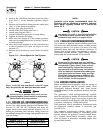
The manufacturer uses an UNGROUNDED AC neu-
tral. Grounding is recommended only at the main
service entrance. If the neutral wire is grounded and
one of the phase loads becomes grounded, the exces-
sive current opens the load circuit breaker or col-
lapses the generator field. The actual result depends
on the electrical characteristics of the particular
installed generator.
2.9 AUTOMATIC TRANSFER SWITCH
(ATS MODE)
When this generator, along with an HS Type automat-
ic transfer switch has been installed and connected,
a circuit board in the generator control panel con-
stantly monitors the utility voltage and controls the
operation of the transfer switch.
To implement this mode of operation, Position 2 of
the eight-position DIP switch, which is located on the
generator circuit board (see Figure 3.2), must be in
the OFF position. In ATS Mode utility voltage sensing,
weekly exercising, and load transferring is under the
control of the generator.
Should the utility voltage drop below a preset value,
and remain at this low voltage for a preset amount of
time, the generator cranks and starts. After the gen-
erator starts, the transfer switch transfers the load
circuits to the generator so the generator can power
them. When the utility source voltage has been
restored, the transfer switch re-transfers the load cir-
cuits back to the utility source voltage and the gener-
ator shuts down.
The HS Type transfer switch is controlled by the gen-
erator circuit board via control wires 23 and 194.
Wire 23 connects the relay driver output (collector of
an NPN transistor) on the generator circuit board to
the "low side" (Terminal 23) of the transfer relay coil
in the transfer switch. Wire 194 connects positive
battery voltage from the generator circuit board to the
"high side" (Terminal 194) of the transfer relay coil in
the transfer switch.
If generator wires 23 and 194 are not wired to
the correct terminals in the transfer switch, the
circuit board in the generator control panel will
be damaged.
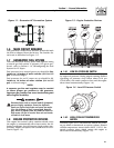
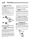
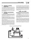
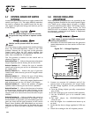
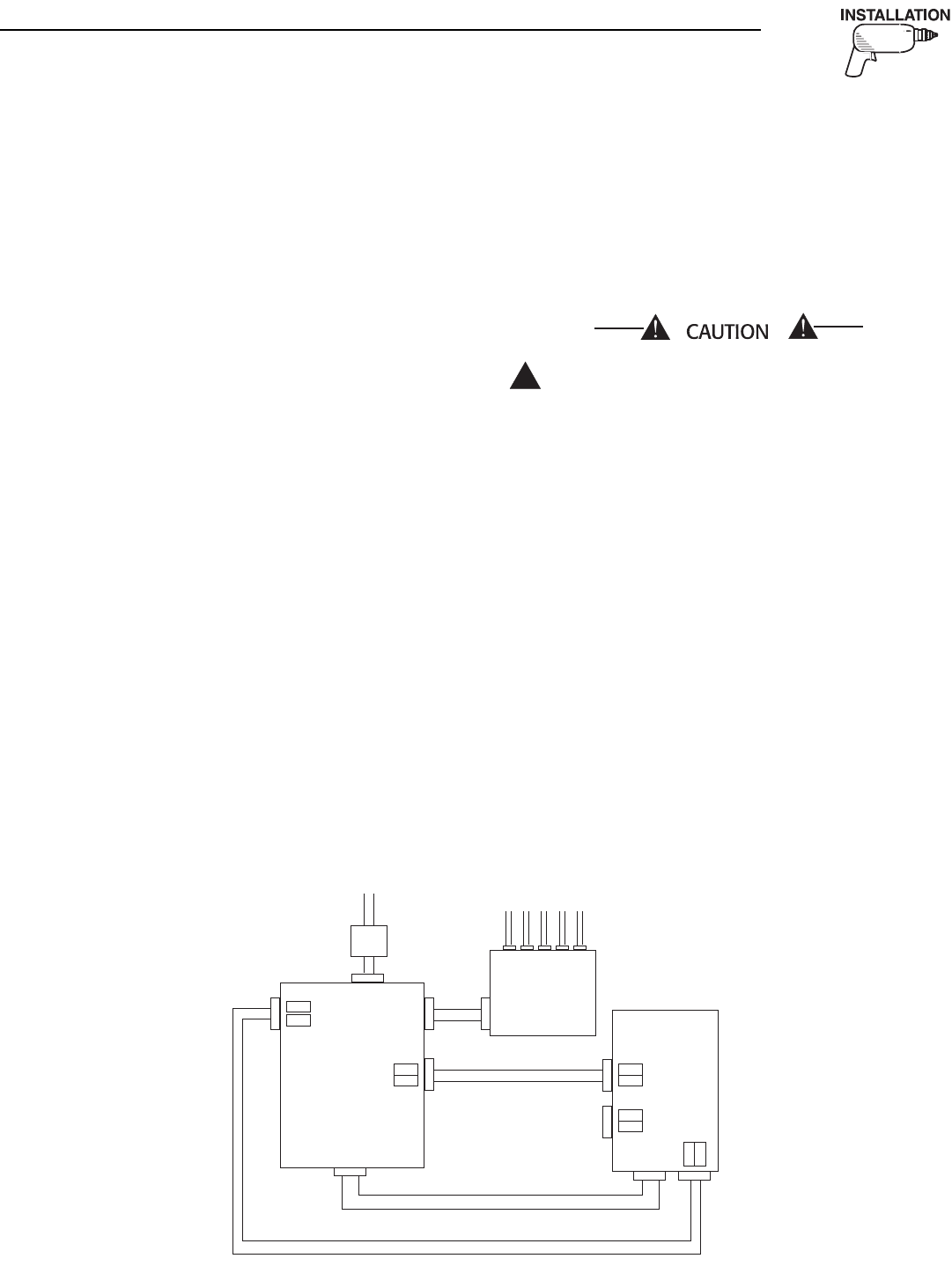
In order for the generator utility voltage sensing and
battery charging functions to work, it is necessary to
provide a 5 amp fused 240Vac utility source connec-
tion from the transfer switch main N1 and N2 termi-
nals to the generator control panel N1 and N2 termi-
nals (See Figure 2.3).
Transfer Switch terminals N1 and N2 (also called
Utility 1 and Utility 2) are the input utility AC power
connections to the Transfer Switch. Transfer Switch
terminals T1 and T2 (also called Load 1 and Load 2)
are the transfer switch AC output power terminals
that go to the load circuit distribution panel. Transfer
Switch terminals E1 and E2 are the AC power termi-
nals that come from the generator's main alternator.
!
Section 2 — Installation
Liquid-cooled 15, 20 and 25 kW Generators
FROM UTILITY
TO LOAD
FEEDER CIRCUITS
LOAD
DISTRIBUTION
PANEL
GENERATOR
194
23
178
183
N2 N1
E1 E2
E1 E2
194
23
N1 N2
N1
N2
FUSE
FUSE
HS TYPE
TRANSFER
SWITCH
T1
T2
MAIN LINE
CIRCUIT
BREAKER
OR FUSE
Figure 2.3 - Connection Diagram (ATS Mode)