


Generac
®
Power Systems, Inc. 5
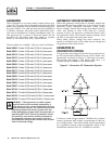
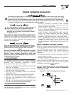
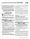
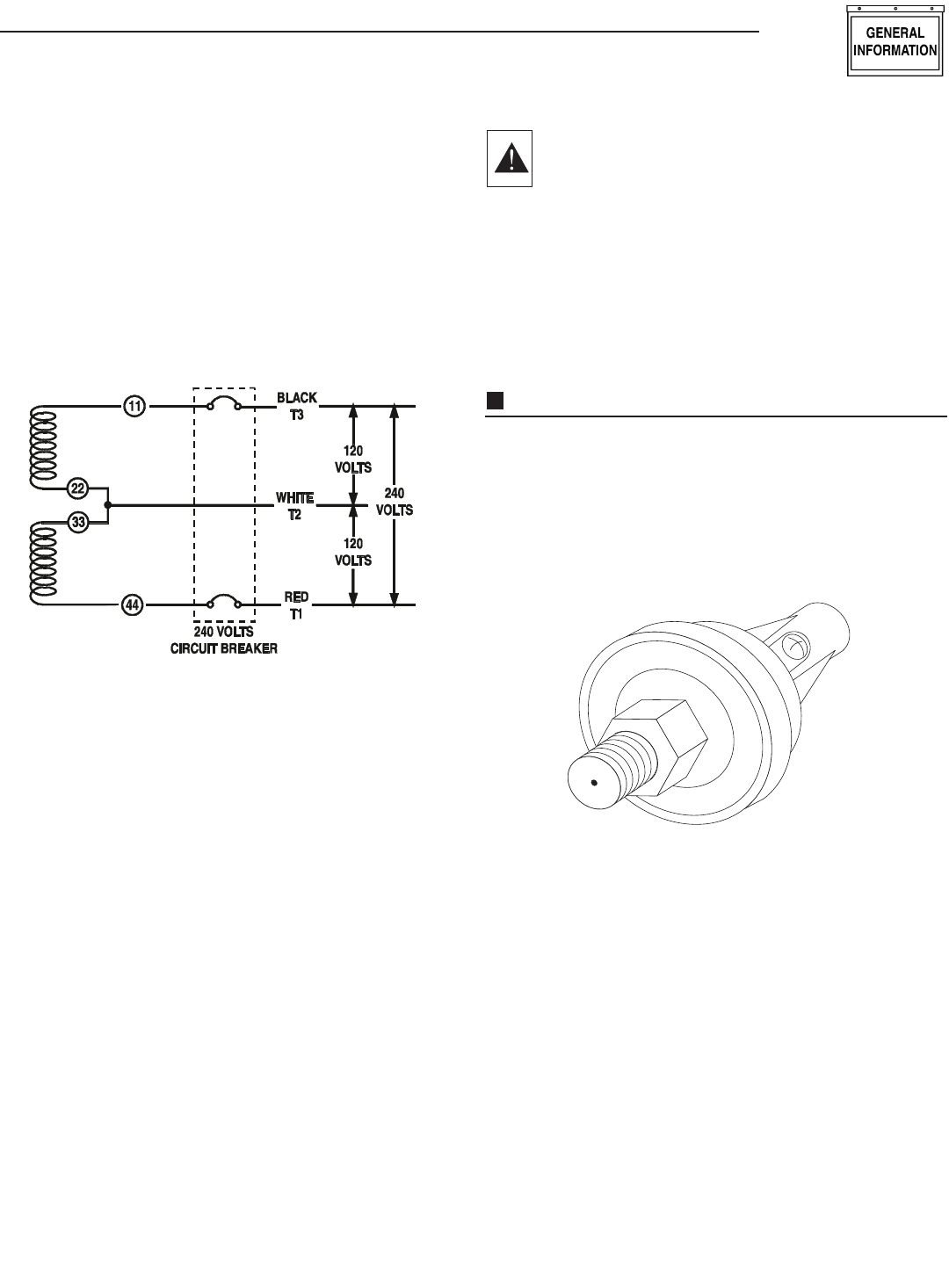
Figure 3 represents a single-phase, 3-wire generator AC
connection system. The stator assembly in this system
consists of a pair of stationary windings, with two leads
brought out of each winding. Each single winding can
supply 120 volts AC, 60 Hertz. When the two windings
are connected in series, a 240 volts, 60 Hertz AC output
results. Typically the two “hot” leads in the circuit are
Wires No. 11 and 44. The “Neutral” leads are the junc-
tion of Wires 22 and 33.
Figure 3 - Generator AC Connection System
MAIN CIRCUIT BREAKER
The generator’s main circuit breaker is included with the unit as
shipped from the factory. The breaker for each unit is described in
Figure 5 below.
GENERATOR FUEL SYSTEM
Your unit has been factory tested and adjusted using a
natural gas fuel system. If propane (LP) gas is pre-
ferred, contact an authorized service dealer.
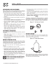
WARNING: Gaseous fuels such as natural and LP
(propane) gas are highly explosive. Even the slightest
spark can ignite such fuels and cause an explosion. No
leakage of fuel is permitted. Natural gas, which is lighter
than air, tends to collect in high areas. LP gas is heavier
than air and tends to settle in low areas.
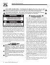
ENGINE PROTECTIVE DEVICES
The engine has several safety switches which cause the
engine to automatically shut down under the following
conditions: low oil pressure, high coolant temperature,
engine overspeed, low coolant level or overcrank.
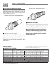
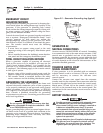
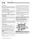
LOW OIL PRESSURE SWITCH:
This switch is normally-closed (N.C.) but is held open
by engine oil pressure during engine running. Should
operating oil pressure drop below about 8-10 psi (55-68
kPa), the switch contacts close and the engine shuts
down automatically (Figure 4).
Figure 4 - Low Oil Pressure Switch
Section 1 - General Information
Guardian Liquid-cooled 10 kW, 15 kW, 20 kW and 25 kW Generators
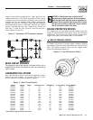
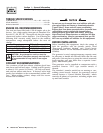
Model Rating Phase Actual Current C/B Rating* % over rating Circuit Breaker
004090-2 10,000 1 41.7 50 120% 50A BQ2
004091-2 10,000 3 30.1 40 133% 40A BQ3
004124-1 10,000 1 41.7 50 120% 50A BQ2
004125-1 10,000 3 30.1 40 133% 40A BQ3
004092-2 15,000 1 62.5 70 112% 70A BQ2
004093-2 15,000 3 45.2 60 133% 60A BQ3
004126-1 15,000 1 62.5 70 112% 70A BQ2
004127-1 15,000 3 45.2 60 133% 60A BQ3
004094-2 20,000 1 83.3 90 108% 90A BQ2
004095-2 20,000 3 60.2 70 116% 70A BQ3
004128-1 20,000 1 83.3 90 108% 90A BQ2
004096-2 25,000 1 104.2 125 120% 125A BQ2
004097-2 25,000 3 75.3 90 120% 90A BQ3
004130-1 25,000 1 104.2 125 120% 125A BQ2
004131-1 25,000 3 75.3 90 120% 90A BQ3
004474-0 25,000 1 104.2 125 120% 125A BQ2
004475-0 25,000 1 104.2 125 120% 125A BQ2
* Amp Rating of C/B structured under model.
Figure 5 - Main Circuit Breaker