


4 Generac
®
Power Systems, Inc.
GENERATOR
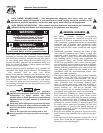
This equipment is an water-cooled, engine-driven gen-
erator set. The generator is designed to supply electrical
power that operates critical electrical loads during util-
ity power failure. The unit has been factory-installed in
a weather resistant, all metal sound attenuated enclo-
sure and is intended for outdoor installation only. Use
this generator as a source of electrical power for the
operation of 120 and/or 240 volts, single or 3-phase
loads, or 120 and/or 208 volts, 3-phase loads.
These models are available. They are rated as follows:
Model 004090: Provides 10,000 watts (10 kW) of 1-phase power.
Model 004091: Provides 10,000 watts (10 kW) of 3-phase power.
Model 004124: Provides 10,000 watts (10 kW) of 1-phase power.
Model 004125: Provides 10,000 watts (10 kW) of 3-phase power.
Model 004092: Provides 15,000 watts (15 kW) of 1 phase power.
Model 004093: Provides 15,000 watts (15 kW) of 3 phase power.
Model 004126: Provides 15,000 watts (15 kW) of 1 phase power.
Model 004127: Provides 15,000 watts (15 kW) of 3 phase power.
Model 004094: Provides 20,000 watts (20 kW) of 1-phase power.
Model 004095: Provides 20,000 watts (20 kW) of 3-phase power.
Model 004128: Provides 20,000 watts (20 kW) of 1-phase power.
Model 004096: Provides 25,000 watts (25 kW) of 1 phase power.
Model 004097: Provides 25,000 watts (25 kW) of 3 phase power.
Model 004130: Provides 25,000 watts (25 kW) of 1 phase power.
Model 004131: Provides 25,000 watts (25 kW) of 3 phase power.
Model 004474: Provides 25,000 watts (25 kW) of 1 phase power.
Model 004475: Provides 25,000 watts (25 kW) of 1 phase power.
WARNING: If this generator is used to power
electrical load circuits normally powered by a
utility power source, you are required by code to
install a transfer switch. The transfer switch must
effectively isolate the electric system from the
utility distribution system when the generator is
operating (NEC 701). Failure to isolate an electri-
cal system by such means results in damage to
the generator and may also result in injury or
even death to utility power workers due to back-
feed of electrical energy.
AUTOMATIC SYSTEM OPERATION
When this generator along with its transfer switch has
been installed and interconnected, a circuit board in the
generator panel constantly monitors utility power
source voltage. Should that voltage drop below a preset
value, and remain at such a low state for a preset
amount of time, the generator cranks and starts. After
the generator starts, the transfer switch transfers load
circuits so the generator can power them.
When utility source voltage has been restored, the
switch re-transfers back to the utility source voltage and
the generator then shuts down.
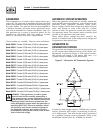
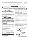
GENERATOR AC
CONNECTION SYSTEMS
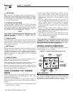
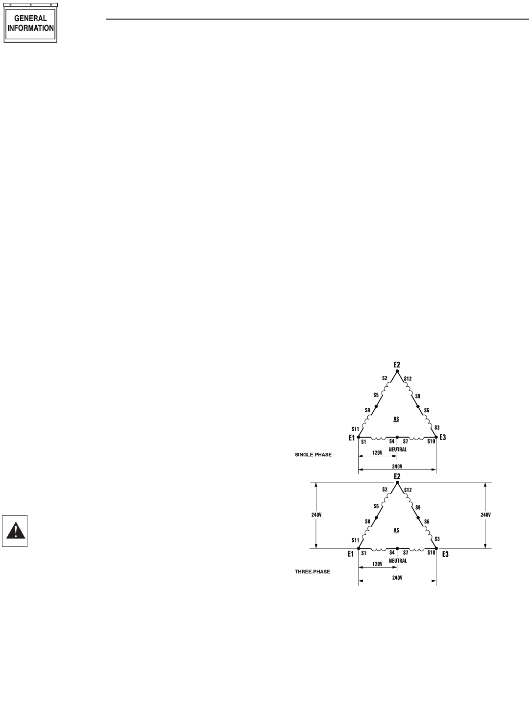
The generator was shipped from the factory with its sta-
tor AC output leads connected in one of the “Delta” con-
figurations, as shown in Figure 2. This type of connec-
tion system will supply a 120 and/or 240 volts, 1 or
3-phase output as shown in the illustration.
Figure 2 - Generator AC Connection System
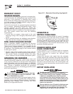
If, however, load voltage requires 120/208 volts, 3-phase
output, generator will require reconnecting of the sta-
tor’s output leads. This task should only be performed
by a qualified Generac service technician. Refer to the
installation manual (Part No. 079699) for details.
Section 1 - General Information
Guardian Liquid-cooled 10 kW, 15 kW, 20 kW and 25 kW Generators