


12 Generac
®
Power Systems, Inc.
Fuel System
Make sure the fuel supply system to the generator (a)
delivers the correct fuel at the correct pressure and (b)
is properly purged and leak tested according to code.
No fuel leakage is permitted. See “Specifications” (Page
7) for more information.
Generator Set Lubrication
Check the engine crankcase oil level before operating
and add oil to the proper level – the dipstick “FULL”
mark. Never operate the engine with the oil level below
the dipstick “ADD” mark. See “Specifications” (Page 7)
and “Engine Oil Recommendations” (Page 8).
NOTE:
This engine is shipped from the manufacturer with
15W-40 oil. This oil should be changed after 30
hours of operation.
Engine Coolant
Have the engine cooling system properly filled with the
recommended coolant mixture. Check the system for
leaks and other problems. See “Specifications” (Page 7)
and “Coolant” (Page 8).
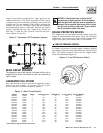
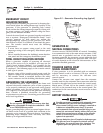
Belt Tension
Check the engine fan belt tension and condition prior to
placing the unit into service and at recommended
intervals. Belt tension is correct when a force of approx-
imately 22 pounds (10 kg), applied midway between
pulleys, deflects the belt about 3/8- to 5/8-inch
(10 to 16 mm).
Electrical System
Make sure the generator is properly connected to an
approved earth ground and/or ground rod.
Make sure the generator battery is fully charged, proper-
ly installed and interconnected, and ready for use.
Check to ensure that there are no loose electrical con-
nections. Restrain any loose wires to keep them clear of
any moving generator set components.
USING A STANDARD “GTS” TRANSFER
SWITCH
When required, the pre-packaged standby generator
can be installed with a standard Generac “GTS” type
automatic transfer switch.
When you use a standard GTS type transfer switch, it
controls automatic operation and automatic transfer as
follows:
• Solid state circuits in the transfer switch monitor util-
ity power source voltage.
• When utility source voltage drops below a pre-set
level, transfer switch action closes the circuit. The
engine then cranks and starts as controlled by the
pre-packaged generator’s Control Module circuit
board.
• After the engine starts and when the generator AC
output voltage and frequency have reached a pre-set
value, transfer switch circuits signal the transfer
switch main contacts to actuate to the “Standby”
power source side. Generator AC output then powers
load circuits.
• When the utility power source voltage is restored
above a pre-set level, transfer switch solid state cir-
cuits signal the switch main contacts to move back to
their utility power source side.
• Following re-transfer back to the utility power source
side, transfer switch circuit board action opens the
circuit. Engine then shuts down.
NOTE:
If your generator is installed in conjunction with a
standard GTS type transfer switch, refer to the
applicable transfer switch manual for exact oper-
ating parameters and timing sequences.
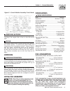
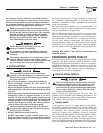
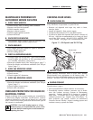
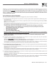
CONTROL CONSOLE COMPONENTS
The components of a water-cooled generator control
console (Figure 8) are as follows:
Figure 8 - Water-Cooled Generator Panel
AC VOLTMETER:
The voltmeter displays generator AC output voltage dur-
ing operation. Voltage is regulated by a solid state volt-
age regulator and is proportional to AC frequency. Refer
to your unit’s DATA PLATE for rated AC voltage.
▼ ▼ ▼ ▼ ▼
Section3—Installation
Guardian Liquid-cooled 10 kW, 15 kW, 20 kW and 25 kW Generators