


10 Generac
®
Power Systems, Inc.
EMERGENCY CIRCUIT
ISOLATION METHOD
This prevents overloading the generator by keeping elec-
trical loads below the wattage/amperage capacity of the
generator. If the generator is powering only critical
loads, within the wattage/amperage capacity, during util-
ity power outages, you might consider using the emer-
gency circuit isolation method.
Critical electrical loads are grouped together and wired
into a separate “Emergency Distribution Panel.” Load
circuits powered by that panel are within the
wattage/amperage capacity of the generator set. When
this method is used, it is difficult to overload the gener-
ator. The transfer switch must meet the following
requirements:
• It must have an ampere rating equal to the total
amperage rating of the emergency distribution panel
circuit.
• Have it installed between the building’s main distribu-
tion panel and the emergency distribution panel.
TOTAL CIRCUIT ISOLATION METHOD
When a generator capable of powering all electrical
loads in the circuit is to be installed, you may use the
“Total Circuit Isolation Method.” It is possible for the
generator to be overloaded when this isolation method
is employed. The following apply to the transfer switch
in this type of system.
• Ampere rating of the transfer switch must equal the
ampere rating of the normal incoming utility service.
• The transfer switch is installed between the utility
service entrance and the building distribution panel.
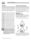
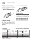
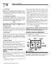
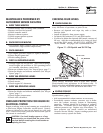
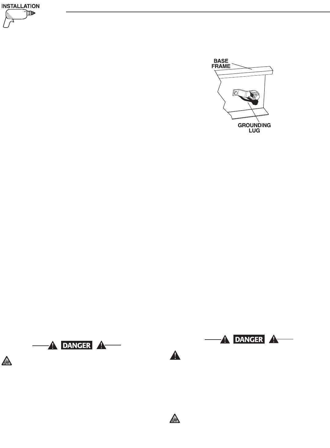
GROUNDING THE GENERATOR
The National Electrical Code requires the frame and
external electrically conductive parts of this equipment
to be properly connected to an approved earth ground
and/or grounding rods. For that purpose, a GROUND
LUG (Figure 2.2) is provided on the generator mounting
base. Consult a qualified electrician for grounding
requirements in your area. Grounding procedures must
meet local regulations.
Do not connect the ground wire to any pipe that
carries a flammable or explosive substance – FIRE
or an EXPLOSION may result.
Proper grounding helps protect personnel against electri-
cal shock in the event of a ground fault condition in the
generator or in connected electrical devices. In addition,
grounding helps dissipate static electricity that often
builds up in ungrounded devices.
Figure 2.2 – Generator Grounding Lug (typical)
GENERATOR AC
NEUTRAL CONNECTIONS
Generac uses an UNGROUNDED AC neutral. Grounding
is recommended only at the main service entrance. If the
neutral wire is grounded and one of the phase loads
becomes grounded, the excessive current opens the load
circuit breaker or collapses the generator field. The actu-
al result depends on the electrical characteristics of the
particular installed generator.
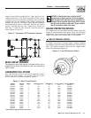
TRANSFER SWITCH START
SIGNAL CONNECTIONS
If your generator is to be installed with an automatic
transfer switch, such as a Generac GTS-type switch, it
will be necessary to connect the two-wire start
control system.
Connect the two-wire start signal from the automatic
transfer switch to the automatic start connection, which is
located in the right hand corner inside the control panel.
Match wires 178 and 183 in the transfer switch to 178
and 183 on the terminal strip in the control panel. The
conductors for the two-wire start circuit must be in their
own conduit.
BATTERY INSTALLATION
Standby generators installed with automatic trans-
fer switches will crank and start automatically
when normal (utility) source voltage is removed or
is below an acceptable preset level. To prevent
such automatic start-up and possible injury to per-
sonnel, do not connect battery cables until you are
certain that normal source voltage at the transfer
switch is correct and you are ready to place the
system into operation.
Storage batteries give off explosive hydrogen gas.
This gas can form an explosive mixture around
the battery for several hours after charging. The
slightest spark can ignite the gas and cause
Section2—Installation
Guardian Liquid-cooled 10 kW, 15 kW, 20 kW and 25 kW Generators