


Generac
®
Power Systems, Inc. 13
AC AMMETER:
Indicated current draw of connected electrical loads
during operation. DO NOT EXCEED YOUR UNIT’S
RATED MAXIMUM CONTINUOUS CURRENT. Refer to
the unit DATA PLATE.
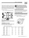
AC FREQUENCY METER:
Indicates generator AC output frequency in “Hertz”
(cycles per second). Frequency is proportional to engine
speed. Units with a 4-pole rotor supplies 60 Hertz at
1800 rpm. Units with a 2-pole rotor supplies 60 Hz at
3600 rpm. Frequency reading with no electrical loads
connected (no-load condition) should be between 59-61
Hertz.
DC VOLTMETER:
The generator is equipped with a belt-driven DC
alternator, which maintains battery state of charge when
the engine operates. The Control Module Assembly also
incorporates a trickle charge circuit which maintains
battery state of charge during non-operating periods.
Battery voltage should read about 12.5 to 14.5 volts DC.
A low battery voltage indicates the battery is
discharging.
HOURMETER:
Indicates time the engine-generator has operated, in
hours and tenths of hours. Use the hourmeter along
with the periodic maintenance schedule for your gener-
ator set.
AUTO/OFF/MANUAL SWITCH:
Use this 3-position switch as follows:
• Set the switch to “Auto” for fully automatic operation.
See “Automatic Operation”.
• Set switch to “Manual” position to crank and start the
generator engine.
• Set switch to “Off” position to shut down an operat-
ing engine. With “Off” selected, operation will not be
possible.
DANGER! With switch set to "auto", engine can
crank and start suddenly without warning. Such
automatic start up normally occurs when utility
source voltage drops below a pre-set level. To
prevent possible injury that might be caused by
such sudden starts, set AUTO/OFF/MANUAL
switch to "off" before working on or around the
unit. Then, place a "do not operate" tag on con-
trol console.
FAULT INDICATOR LAMP:
Lamp goes ON when one or more of the following
engine faults occurs and when engine shuts down.
• Low oil pressure • Overcrank
• High coolant temperature • Overspeed
• Low coolant level
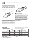
30 AMP FUSE:
Fuse protects the control console’s DC control circuit
against electrical overload. If the fuse has melted open
because of an overload, engine cranking and startup
cannot occur. Should you need to replace the fuse, use
only an identical 30-amp replacement fuse. (Type AGC)
7.5 AMP INLINE FUSE:
A 7.5 Amp inline fuse has been added to the wire har-
ness of all units starting in the second half of 2001. This
inline fuse is connected in the 15A line that runs
between the Auto/Off/Manual switch and position 10 of
the 76009A PCB. This fuse protects the start, fuel, field
boost, and transfer outputs from the PCB and will open
if there is excessive current draw on any one of these
outputs.
NOTE:
This fuse will not remove the + battery input
power from the PCB when it opens. This means the
exercise timer will not be reset. If this fuse does
open, carefully check the wiring to the start, fuel,
field boost and transfer outputs before replacing
the fuse.
METER READING SELECTOR SWITCH:
Switch permits you to select either line-to-line or
line-to-neutral voltage and amperage readings on the
console AC voltmeter and AC ammeter.
SET EXERCISE TIME SWITCH:
Switch allows you to program the generator to start and
exercise automatically. “See Weekly Exercise Cycle.”
MANUAL TRANSFER AND START UP
To transfer electrical loads to the “Standby” (generator)
power source side and start the engine manually, refer
to the Owner’s Manual of your particular transfer
switch.
Section 3 - Operation
Guardian Liquid-cooled 10 kW, 15 kW, 20 kW and 25 kW Generators