5
Figure 3 – Starter Connection
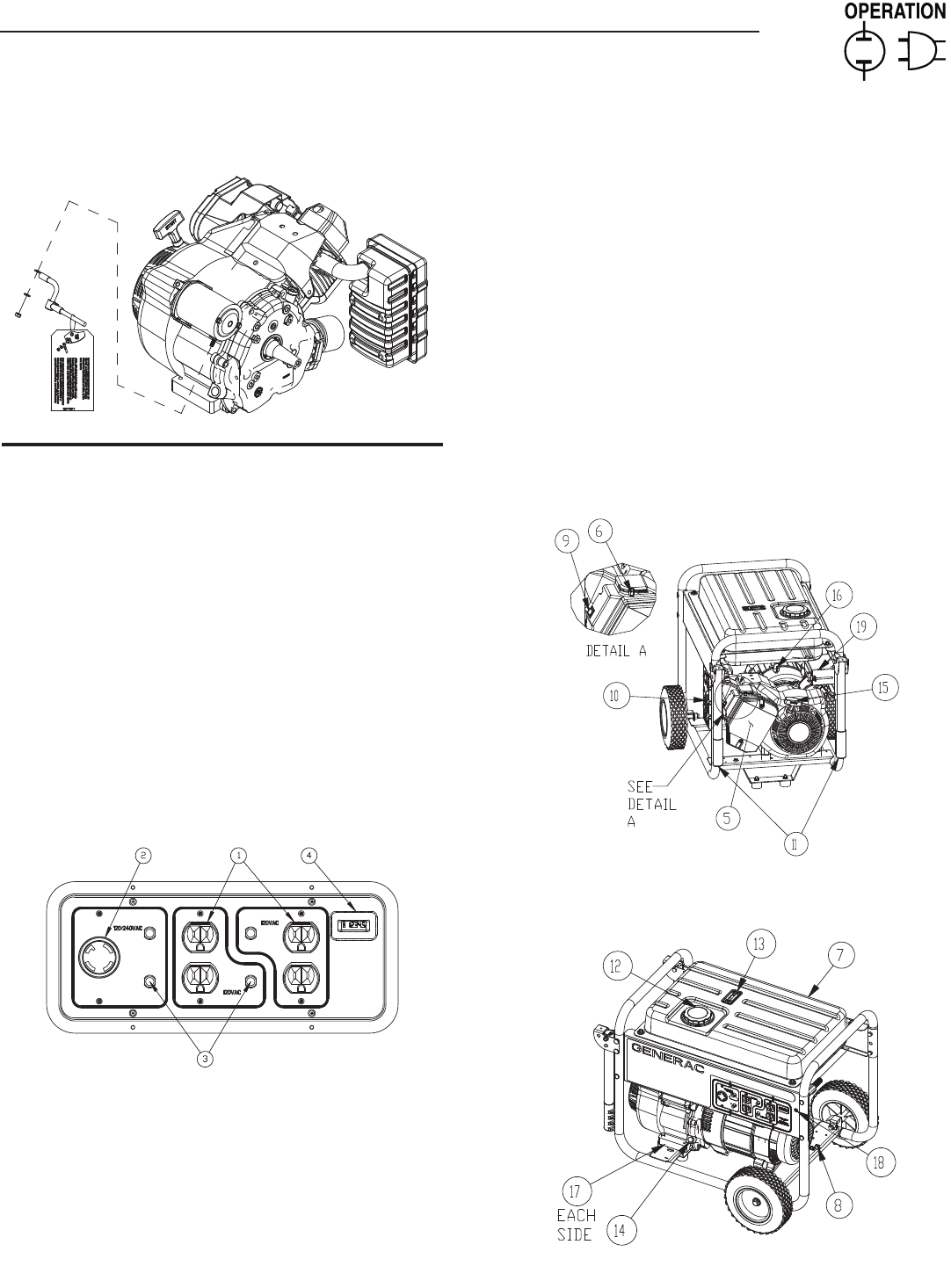
2.1 KNOW THE GENERATOR
Read the Owner’s Manual and Safety Rules before operating
this generator.
Compare the generator to Figures 4 through 6 to become
familiarized with the locations of various controls and adjustments.
Save this manual for future reference.
1. 120 Volt AC, 20 Amp, Duplex Receptacle – Supplies electrical
power for the operation of 120 Volt AC, 20 Amp, single-phase,
60 Hz electrical lighting, appliance, tool and motor loads.
2. 120/240 Volt AC, 30 Amp Locking Receptacle – Supplies
electrical power for the operation of 120 and/or 240 Volt AC,
30 Amp, single-phase, 60 Hz, electrical lighting, appliance,
tool and motor loads.
3. Circuit Breakers (AC) – Each receptacle is provided with a
push-to-reset circuit breaker to protect the generator against
electrical overload.
Figure 4 - Control Panel
4. Hourmeter – Tracks hours of operation.
5. Air Filter – Filters intake air as it is drawn into the engine.
6. Choke Knob – Used when starting a cold engine.
7. Fuel Tank – Tank holds 6.6 U.S. gallons of fuel.
8. Grounding Lug – Ground the generator to an approved earth
ground here. See "Grounding the Generator" for details.
9. Run/Stop Switch – Controls the operation of the generator.
10. Muffler – Quiets the engine.
11. Handles – Pivot and retract for storage. Press the spring-
loaded button to move handles.
12. Gas Cap – Fuel fill location.
13. Fuel Gauge – Shows fuel level in tank.
14. Oil Fill – Add oil here.
15. Recoil Starter – Use to start engine manually.
16. Fuel Shut Off – Valve between fuel tank and carburetor.
17. Oil Drain – Use to drain engine oil.
18*. Battery Charger Input – This receptacle allows the capability
to recharge the 12 volt DC storage battery provided with
the 12 Volt Adaptor Plug Charger which is included in the
Accessory Box. Located behind the battery charger input is
a 1.50 Amp in-line fuse which is inside the control panel to
protect the battery.
19*. Battery – Powers the electric starter.
* Electric start only.
Figure 5 - Generator Controls
Figure 6 - Generator Controls
Section 2 – Operation
Portable Generator System


